
3D printed RC aircraft · Revision 0.2.0 · Bench review
Raven Kestrel
A high-wing aircraft with four lift motors, a rear cruise propeller and removable wing-to-pod fairings.
The latest bench CAD is shown in the preview. The build guide and member kit use 0.2.0.
- Wingspan
- 1,320 mm
- Wing section
- NACA 2412
- Configuration
- 4+1 lift and cruise
Illustrated guide, bill of materials, STLs and Bambu Studio projects in one ZIP.
Loading the 3D view…
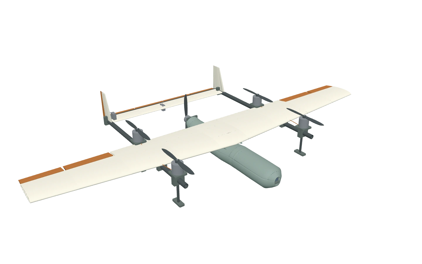
Exploded view inventoryAft rim bench candidate
- Airframe
- The 0.2.0 twin-boom airframe, with the revised rear crown and aft pod rim.
- Fasteners and linkages
- Keyed rails, seam pins and detents, fairing screws and insert locations, and lift motor screw locations.
- Electronics and wiring
- Lift and cruise propulsion, ESCs, flight controller, battery, receiver, GNSS, servos and schematic harness routing.
- Items to check in the build guide
- Check fairing insert fit and seam-pin retention. Use the bill of materials for the airspeed kit, power distribution, cruise motor mounting and propeller retainers.
A twin-boom aircraft with separate lift and cruise motors
- Airframe
- Two booms carry the H-tail. Removable port and starboard fairings seat on fixed anchor shoes. Keyed guides align the two main fuselage seams and captive pins lock them.
- How it’s controlled
- The SpeedyBee F405 WING APP uses four DShot300 lift outputs and separate PWM outputs for cruise throttle, two ailerons, elevator and starboard rudder. CRSF uses UART1, GNSS uses UART3, and the compass and differential pressure sensor use I²C. The external Castle BEC supplies the isolated servo positive rail. Record the controller firmware and confirm each function on the bench.
- Who it’s for
- For RC builders comparing independent lift and cruise systems and checking keyed fuselage rails and captive pins at the bench.
- Flight targets
- No range, speed or altitude targets are published for this revision.
Physical checks are pending for print fit, retention, installed power, mass and balance, hover, both transitions, and landing.
Print files
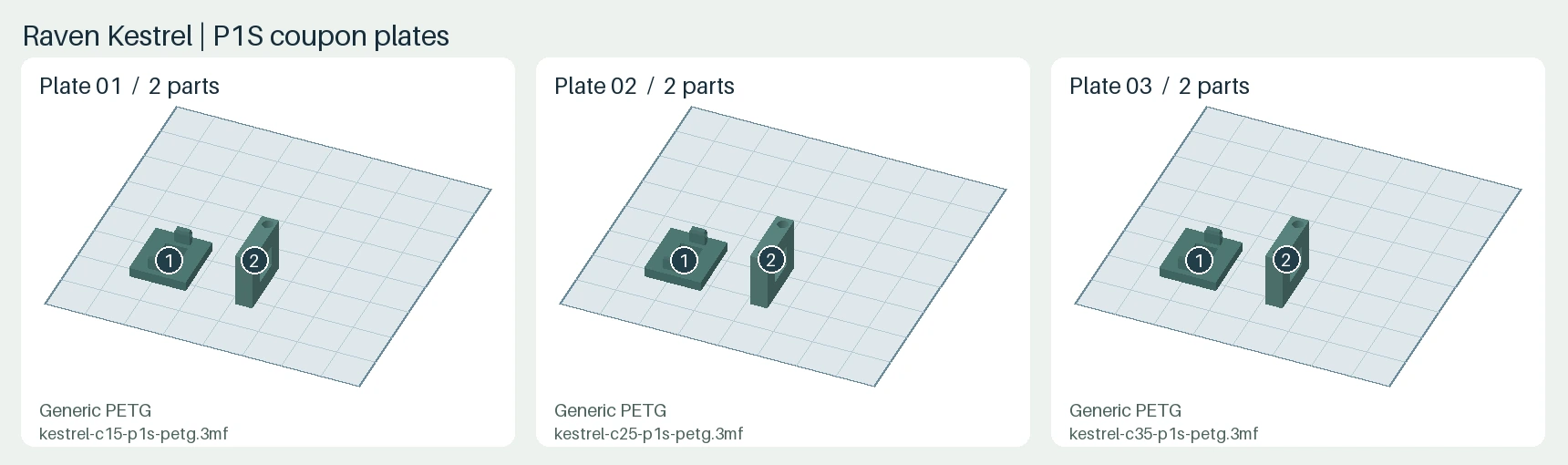
The member build kit contains the listed STLs and print setup. Start with the joint coupons and record the measured fit before selecting an interface for the bench assembly.
Print setup
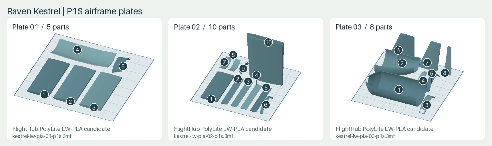
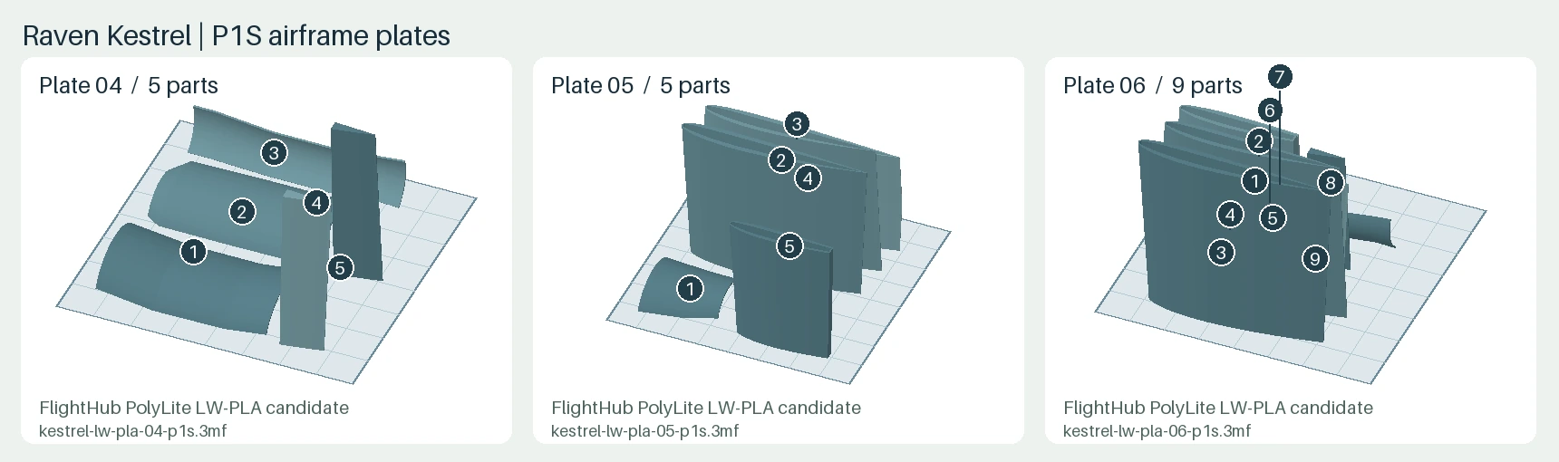
- Bambu Lab P1S with a 0.4 mm nozzle. Start with the saved 0.15, 0.25 and 0.35 mm clearance coupon projects. The coupon profiles use Generic PETG on textured PEI at 0.20 mm layers, four walls and 30% gyroid. The 9 editable airframe plates were checked with Bambu Studio 02.09.01.70. Verify material, bed, supports and orientation on your own printer. Record the physical print, fit, retention, mass and balance before applying power.
View the 80 printed parts
Images show the exported meshes for this revision. Each part is shown at its own scale.
| Part and STL filename | Image | Quantity | Material |
|---|---|---|---|
Nose battery pod lower shellparts/airframe/nose-pod.stl | 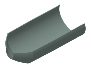 | 1 | LW-PLA candidate |
Nose battery pod front crownparts/airframe/nose-pod-front-crown.stl | 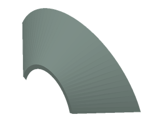 | 1 | LW-PLA candidate |
Nose battery pod hatchparts/airframe/nose-pod-hatch.stl | 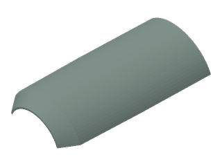 | 1 | LW-PLA candidate |
Nose battery pod rear crownparts/airframe/nose-pod-rear-crown.stl | 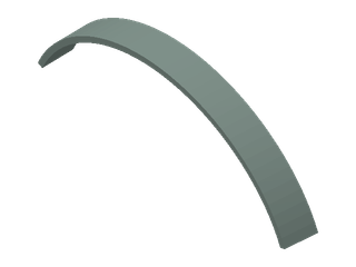 | 1 | LW-PLA candidate |
Center avionics port side shellparts/airframe/center-pod.stl | 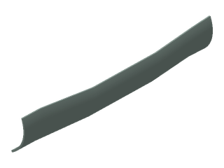 | 1 | LW-PLA candidate |
Center avionics starboard side shellparts/airframe/center-pod-starboard.stl | 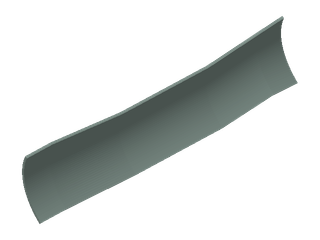 | 1 | LW-PLA candidate |
Center avionics front crownparts/airframe/center-pod-front-crown.stl | 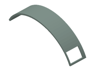 | 1 | LW-PLA candidate |
Center avionics roofparts/airframe/center-pod-roof.stl | 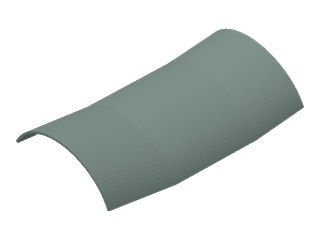 | 1 | LW-PLA candidate |
Center avionics rear crownparts/airframe/center-pod-rear-crown.stl | 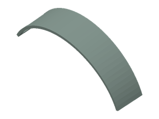 | 1 | LW-PLA candidate |
Center avionics front bellyparts/airframe/center-pod-front-belly.stl | 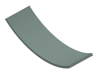 | 1 | LW-PLA candidate |
Center avionics hatchparts/airframe/center-pod-hatch.stl | 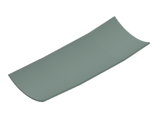 | 1 | LW-PLA candidate |
Center avionics rear bellyparts/airframe/center-pod-rear-belly.stl | 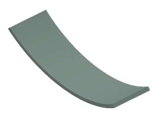 | 1 | LW-PLA candidate |
Aft pusher pod lower shellparts/airframe/aft-pod.stl | 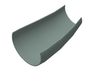 | 1 | LW-PLA candidate |
Aft pusher pod front crownparts/airframe/aft-pod-front-crown.stl | 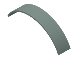 | 1 | LW-PLA candidate |
Aft pusher pod hatchparts/airframe/aft-pod-hatch.stl | 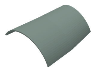 | 1 | LW-PLA candidate |
Aft pusher pod rear crownparts/airframe/aft-pod-rear-crown.stl | 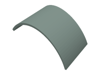 | 1 | LW-PLA candidate |
Center transfer rail, portparts/airframe/center-rail-port.stl | 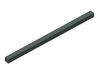 | 1 | PETG candidate for bench fit |
Battery tray guide, portparts/airframe/nose-guide-port.stl | 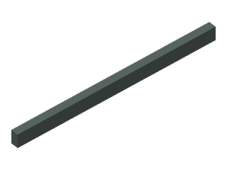 | 1 | PETG candidate for bench fit |
Pusher module transfer rail, portparts/airframe/aft-rail-port.stl | 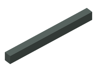 | 1 | PETG candidate for bench fit |
Center transfer rail, starboardparts/airframe/center-rail-starboard.stl | 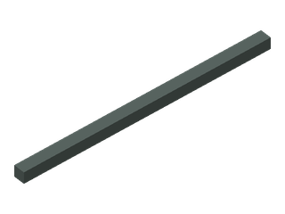 | 1 | PETG candidate for bench fit |
Battery tray guide, starboardparts/airframe/nose-guide-starboard.stl | 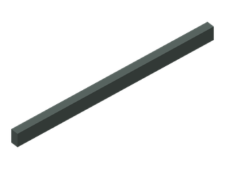 | 1 | PETG candidate for bench fit |
Pusher module transfer rail, starboardparts/airframe/aft-rail-starboard.stl | 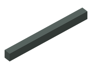 | 1 | PETG candidate for bench fit |
Nose battery tray with strap attachment holesparts/airframe/battery-tray.stl | 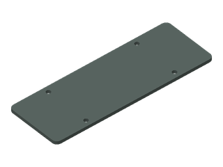 | 1 | PETG candidate for bench fit |
Center avionics mounting trayparts/airframe/avionics-tray.stl | 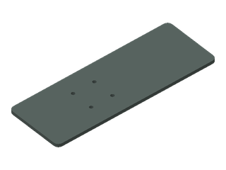 | 1 | PETG candidate for bench fit |
Pusher ESC installation trayparts/airframe/aft-esc-tray.stl | 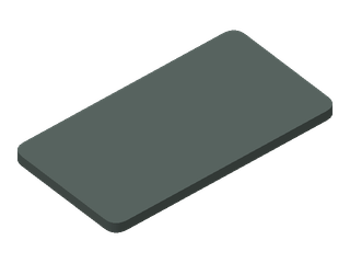 | 1 | PETG candidate for bench fit |
Center wing shell over avionics podparts/airframe/wing-center.stl | 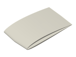 | 1 | LW-PLA candidate |
Wing port panel 1parts/airframe/wing-port-1.stl | 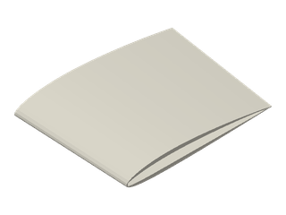 | 1 | LW-PLA candidate |
Wing port panel 2parts/airframe/wing-port-2.stl | 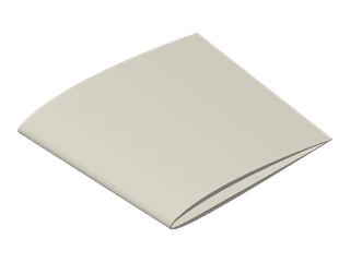 | 1 | LW-PLA candidate |
Wing port panel 3parts/airframe/wing-port-3.stl | 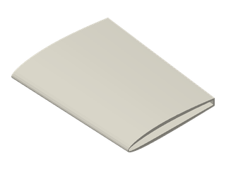 | 1 | LW-PLA candidate |
Aileron port section 1parts/airframe/aileron-port-1.stl | 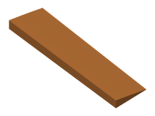 | 1 | LW-PLA candidate |
Wing port panel 4parts/airframe/wing-port-4.stl | 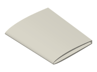 | 1 | LW-PLA candidate |
Aileron port section 2parts/airframe/aileron-port-2.stl | 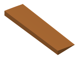 | 1 | LW-PLA candidate |
port front boom collarparts/airframe/boom-saddle-port-front.stl | 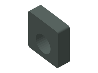 | 1 | PETG candidate for bench fit |
port rear boom collarparts/airframe/boom-saddle-port-rear.stl | 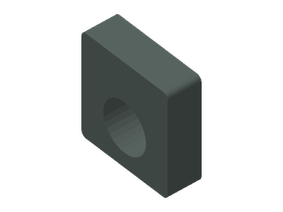 | 1 | PETG candidate for bench fit |
port tail boom collarparts/airframe/boom-saddle-port-tail.stl | 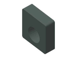 | 1 | PETG candidate for bench fit |
port fore landing footparts/airframe/skid-port-fore.stl | 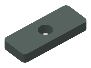 | 1 | PETG candidate for bench fit |
port aft landing footparts/airframe/skid-port-aft.stl | 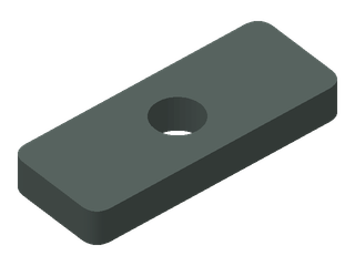 | 1 | PETG candidate for bench fit |
Horizontal stabilizer port section 1parts/airframe/stabilizer-port-1.stl | 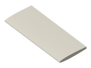 | 1 | LW-PLA candidate |
Linked elevator port section 1parts/airframe/elevator-port-1.stl | 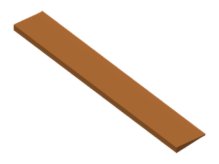 | 1 | LW-PLA candidate |
Horizontal stabilizer port section 2parts/airframe/stabilizer-port-2.stl | 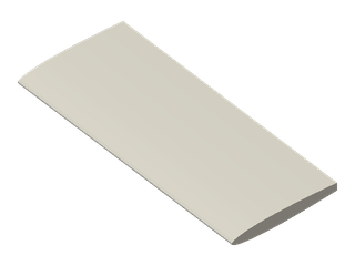 | 1 | LW-PLA candidate |
Linked elevator port section 2parts/airframe/elevator-port-2.stl | 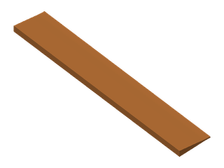 | 1 | LW-PLA candidate |
Vertical fin, portparts/airframe/fin-port.stl | 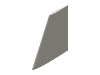 | 1 | LW-PLA candidate |
Wing starboard panel 1parts/airframe/wing-starboard-1.stl | 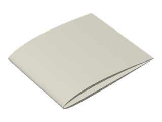 | 1 | LW-PLA candidate |
Wing starboard panel 2parts/airframe/wing-starboard-2.stl | 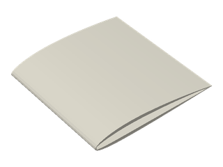 | 1 | LW-PLA candidate |
Wing starboard panel 3parts/airframe/wing-starboard-3.stl | 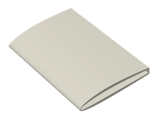 | 1 | LW-PLA candidate |
Aileron starboard section 1parts/airframe/aileron-starboard-1.stl | 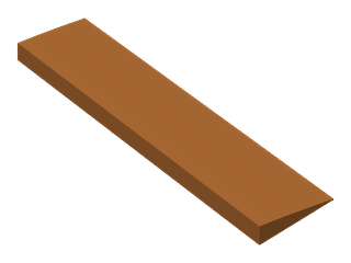 | 1 | LW-PLA candidate |
Wing starboard panel 4parts/airframe/wing-starboard-4.stl | 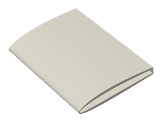 | 1 | LW-PLA candidate |
Aileron starboard section 2parts/airframe/aileron-starboard-2.stl | 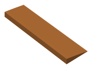 | 1 | LW-PLA candidate |
starboard front boom collarparts/airframe/boom-saddle-starboard-front.stl | 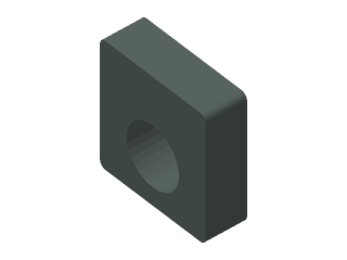 | 1 | PETG candidate for bench fit |
starboard rear boom collarparts/airframe/boom-saddle-starboard-rear.stl | 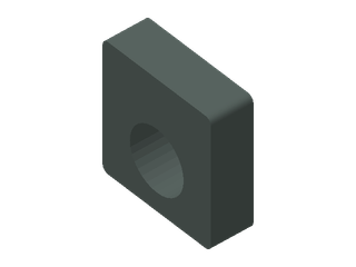 | 1 | PETG candidate for bench fit |
starboard tail boom collarparts/airframe/boom-saddle-starboard-tail.stl | 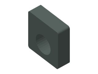 | 1 | PETG candidate for bench fit |
starboard fore landing footparts/airframe/skid-starboard-fore.stl | 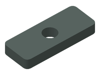 | 1 | PETG candidate for bench fit |
starboard aft landing footparts/airframe/skid-starboard-aft.stl | 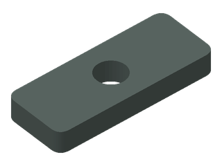 | 1 | PETG candidate for bench fit |
Horizontal stabilizer starboard section 1parts/airframe/stabilizer-starboard-1.stl | 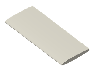 | 1 | LW-PLA candidate |
Linked elevator starboard section 1parts/airframe/elevator-starboard-1.stl | 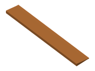 | 1 | LW-PLA candidate |
Horizontal stabilizer starboard section 2parts/airframe/stabilizer-starboard-2.stl | 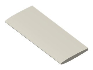 | 1 | LW-PLA candidate |
Linked elevator starboard section 2parts/airframe/elevator-starboard-2.stl | 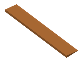 | 1 | LW-PLA candidate |
Vertical fin, starboardparts/airframe/fin-starboard.stl | 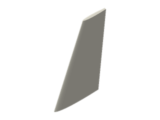 | 1 | LW-PLA candidate |
Starboard rudderparts/airframe/rudder-starboard.stl | 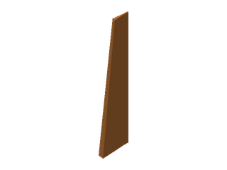 | 1 | LW-PLA candidate |
Lift boom collar, port-foreparts/airframe/lift-cradle-port-fore.stl | 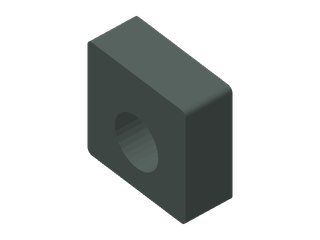 | 1 | PETG candidate for bench fit |
19 × 19 mm lift motor drill plate, port-foreparts/airframe/lift-plate-port-fore.stl | 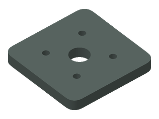 | 1 | PETG candidate for bench fit |
Lift boom collar, port-aftparts/airframe/lift-cradle-port-aft.stl | 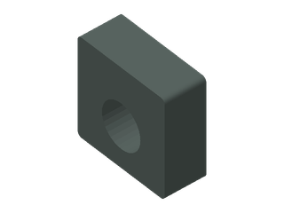 | 1 | PETG candidate for bench fit |
19 × 19 mm lift motor drill plate, port-aftparts/airframe/lift-plate-port-aft.stl | 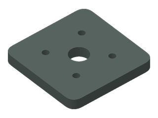 | 1 | PETG candidate for bench fit |
Lift boom collar, starboard-foreparts/airframe/lift-cradle-starboard-fore.stl | 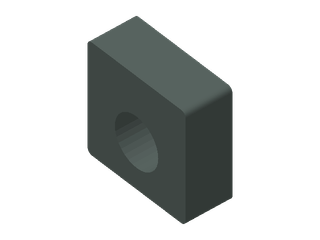 | 1 | PETG candidate for bench fit |
19 × 19 mm lift motor drill plate, starboard-foreparts/airframe/lift-plate-starboard-fore.stl | 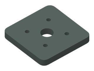 | 1 | PETG candidate for bench fit |
Lift boom collar, starboard-aftparts/airframe/lift-cradle-starboard-aft.stl | 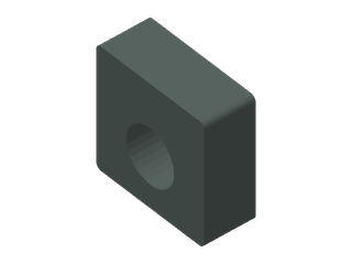 | 1 | PETG candidate for bench fit |
19 × 19 mm lift motor drill plate, starboard-aftparts/airframe/lift-plate-starboard-aft.stl | 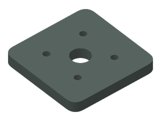 | 1 | PETG candidate for bench fit |
Pusher firewall blank, drill pattern pending motor sampleparts/airframe/pusher-firewall.stl | 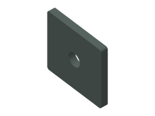 | 1 | PETG candidate for bench fit |
port detachable wing-to-pod shoulder fairingparts/airframe/wing-pod-fairing-port.stl | 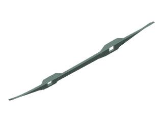 | 1 | LW-PLA candidate |
port conformal roof-bonded anchor shoe 1 (remains for A and B)parts/airframe/wing-pod-fairing-port-anchor-1.stl | 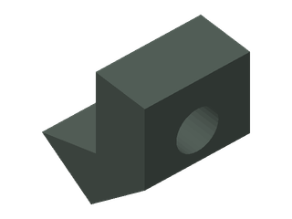 | 1 | PETG candidate |
port conformal roof-bonded anchor shoe 2 (remains for A and B)parts/airframe/wing-pod-fairing-port-anchor-2.stl | 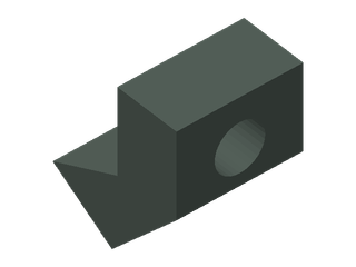 | 1 | PETG candidate |
starboard detachable wing-to-pod shoulder fairingparts/airframe/wing-pod-fairing-starboard.stl | 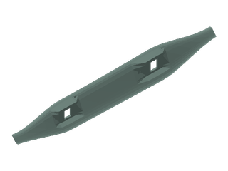 | 1 | LW-PLA candidate |
starboard conformal roof-bonded anchor shoe 1 (remains for A and B)parts/airframe/wing-pod-fairing-starboard-anchor-1.stl | 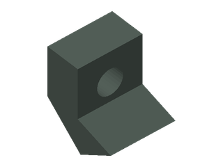 | 1 | PETG candidate |
starboard conformal roof-bonded anchor shoe 2 (remains for A and B)parts/airframe/wing-pod-fairing-starboard-anchor-2.stl | 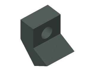 | 1 | PETG candidate |
Spigotparts/coupons/kestrel-c15-spigot.stl | 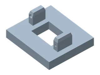 | 1 | PETG candidate |
Receiverparts/coupons/kestrel-c15-receiver.stl | 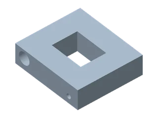 | 1 | PETG candidate |
Spigotparts/coupons/kestrel-c25-spigot.stl | 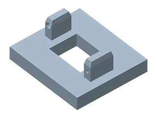 | 1 | PETG candidate |
Receiverparts/coupons/kestrel-c25-receiver.stl | 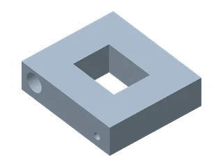 | 1 | PETG candidate |
Spigotparts/coupons/kestrel-c35-spigot.stl | 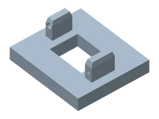 | 1 | PETG candidate |
Receiverparts/coupons/kestrel-c35-receiver.stl | 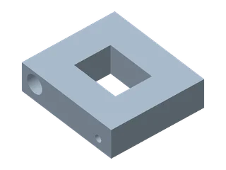 | 1 | PETG candidate |
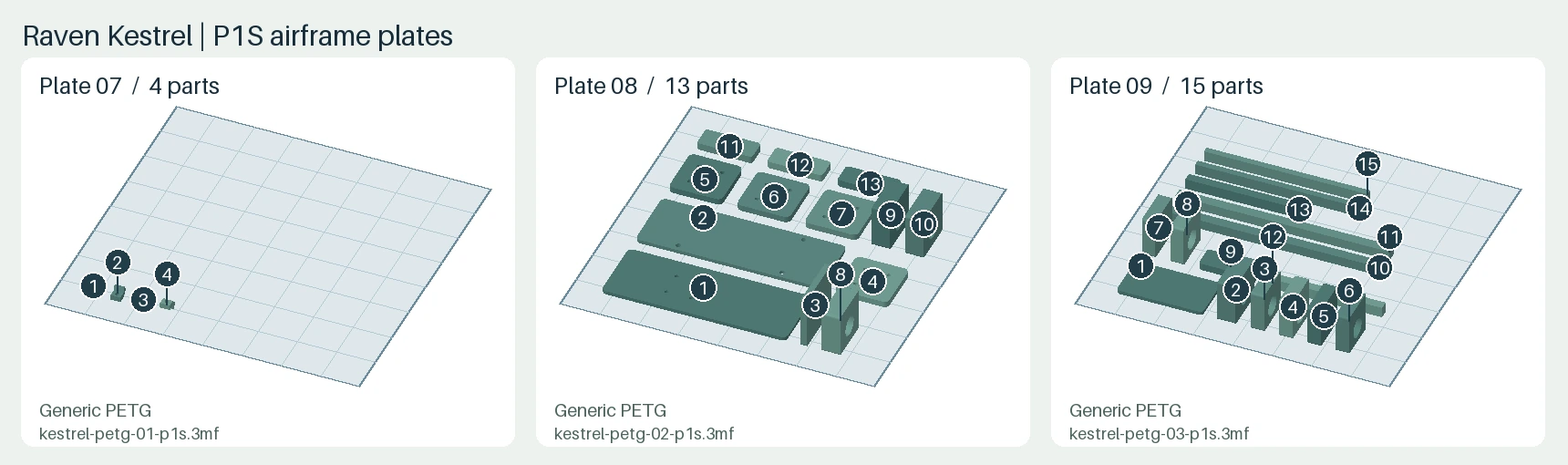
P1S plate setup and orientation
Bambu Studio 02.09.01.70 sliced 9 airframe plates with 5,043 total layers. Estimated filament use is 1343.1 g across the airframe plates, including supports and brims. The 3 fit-coupon projects are separate.
All airframe and coupon plates completed without plate warnings.
View the verified P1S plate layouts
Workshop tools
Use your existing workshop equipment where suitable. The reference printer and these tools are budgeted separately.
- Bambu Lab P1S and calibrated calipers: Stock 0.4 mm nozzle. Log actual printer and slicer revision and measure fit coupons first. bench equipment Reference for Bambu Lab P1S and calibrated calipers
- Guarded thrust stand and electrical instruments: Current-limited props-off source and separate guarded stand with thrust, voltage, current, RPM and temperature logging plus remote power isolation. bench equipment
- Commissioning computer and microSD: Use a pinned ArduPilot build and ground station. Store the revision, channel map, calibration and measured logs. bench equipment Reference for Commissioning computer and microSD
Bill of materials
Aircraft parts, assembly supplies, and radio and charging gear for revision 0.2.0.
Printed-part images show the exported meshes. Hardware and supply drawings help identify items. Images are not to scale.
Download BOM (CSV)Scroll each table sideways to see specifications and supplier links.
Printed parts and filament11 items
| Item | Image | Qty | Price (USD) and stock | Specification & sourcing |
|---|---|---|---|---|
| Kestrel rail and captive-pin fit coupons | Nominal c25 spigot | 1 set | Print from the kit | Two seam stations with mating guide, shoulder, detent and pin samples. Measure repeatability in the intended interface material. print first |
| Nose center and aft fuselage shells | Nose battery pod lower shell | 1 assembly | Print from the kit | Removable nose and aft shell with keyed guides seated against the central module. Verify seams and connector access. prototype CAD |
| Keyed bulkheads and rail carriers | Center transfer rail, port | 2 interfaces | Print from the kit | Rigid guide faces, positive shoulders, replaceable detents and independently inspectable captive pins. prototype CAD |
| Battery hatch and tray plus avionics supports | Nose battery tray with strap attachment holes | 1 set | Print from the kit | 150 × 50 × 38 mm battery case reserve, separate connector exit, tray stops, strap paths and accessible cooling and wiring. prototype CAD |
| Wing panels and ailerons | Wing port panel 1 | 1 set | Print from the kit | 1,320 mm nominal NACA 2412 high wing with two separately driven ailerons. Spar and hinges require fit and structural checks. prototype CAD |
| H-tail horizontal tail and twin fins | Horizontal stabilizer port section 1 | 1 set | Print from the kit | Center elevator and starboard rudder with fixed port fin. Confirm installed propeller and linkage clearance through loaded travel. prototype CAD |
| Motor adapters and skid structures | Lift boom collar, port-fore | 1 set | Print from the kit | Four lift adapters and one pusher firewall tied to the internal frame. Landing loads bypass the cosmetic skins. prototype CAD |
| Lightweight shell filament | 1 lot | $41.14 1097.503 g at $0.037/g $29.99 / 800 g spool In stock Recheck stock · In stock at last check | LW-PLA class candidate. Record exact product and lot after trial shells are weighed and checked for adhesion. material pending The gray 800 g PA08003 variant shows 121 spools. Start with two spools for the 1,097.503 g slice estimate. | |
| Rigid airframe filament (PETG) | 1 lot | $4.66 245.632 g at $0.019/g $18.99 / 1000 g spool In stock Recheck stock · In stock at last check | Use the saved Generic PETG airframe projects as the process reference. Choose and record the actual PETG spool. The three fit coupon projects have separate material estimates. material candidate GigaParts lists the black 1 kg spooled PETG HF G02-K0-1.75-1000-SPL in stock. | |
| Removable port and starboard fairing shells | port detachable wing-to-pod shoulder fairing | 2 | Print from the kit | Two mirrored LW-PLA candidate shells at X215–330 mm. Dry-fit and measure actual wall quality, mass, seam clearance and retention. Successor bench CAD |
| Conformal fairing anchor shoes | port conformal roof-bonded anchor shoe 1 (remains for A and B) | 4 | Print from the kit | Four PETG candidate shoes, two per side at X246 and X296 mm. The Ø3.2 × 4.4 mm insert bore and 0.45 mm adhesive gap are nominal sizing witnesses. Shoes stay on the successor crown in both A and B. Successor bench CAD |
Propulsion and onboard electronics14 items
| Item | Image | Qty | Price (USD) and stock | Specification & sourcing |
|---|---|---|---|---|
| EMAX ECO II 2807 1300 KV lift motor | 4 | $19.49 / motor 4 × $19.49 = $77.96 In stock Recheck stock · In stock at last check | ECO228071300 or global code 0101096021. 3–6S, M3 on 19 × 19 mm, M5 nut, 18 AWG 200 mm leads. Bench thrust and current open. sourced candidate The USA storefront shows 161 units of the exact 1300 KV ECO228071300 variant. | |
| APC 7 × 4 lift propeller bundle | 1 set | Price unconfirmed Stock unconfirmed | LP07040E-B4 includes two standard and two reverse propellers with adapter rings. Confirm fitted retainer and measured RPM. sourced candidate APC lists the LP07040E-B4 four-pack. The live storefront did not provide stock or a current price during the check. | |
| Hobbywing XRotor FPV G2 45A 4in1 lift ESC | 1 | $114.99 / ESC In stock Recheck stock · In stock at last check | 30902065 standalone AM32. 3–6S, DShot300, 40 × 33 × 5 mm, 20 × 20 mm M3, no BEC. Factory XT60 branch and airflow need qualification. sourced candidate Hobbywing North America lists the exact 30902065 20 × 20 mm G2 variant in stock. | |
| BadAss 2315 cruise motor | 1 | $40.69 / motor In stock Recheck stock · In stock at last check | BA-2315-1110. Published Ø29.1 × 32.6 mm before adapter and 16 × 19 mm mounting. Confirm received KV because listing conflicts with spec table. sourced candidate Innov8tive Designs lists BA-2315-1110 in stock. | |
| APC 8 × 6 reverse propeller | 1 | $2.92 / propeller In stock Recheck stock · In stock at last check | LP08060EP. 203.2 mm diameter, Thin Electric reverse rotation. Fit and bench-test the actual pusher orientation and hub stack. sourced candidate Horizon lists six APC08060EP thin-electric pusher propellers on hand. | |
| Hobbywing Skywalker 40A V2 cruise ESC | 1 | $19.99 / ESC In stock Recheck stock · In stock at last check | 80060022. 3–4S, 40 A continuous, 60 × 25 × 8 mm. PWM signal and ground only at flight controller, with its BEC positive isolated. sourced candidate Altitude Hobbies lists the exact 40 A V2 UBEC SKU 80060022 in stock. | |
| CNHL G+Plus 4S 3000 mAh LiPo | 1 | $22.99 / battery In stock Recheck stock · In stock at last check | 300704. XT90, 10 AWG, 136 × 45 × 32 mm nominal, 323 ±5 g. Measure terminal voltage, fit and installed current path. restrained bench candidate CNHL lists the 300704 US warehouse variant with an XT90 connector in stock. | |
| Main distribution and branch harness | 1 set | Source to choose | Qualify the connector assembly, protection, branch wires and total current measurement before simultaneous motor operation. Include restrained short power runs and labeled phase harnesses. release blocked The build specifies qualification of the power distribution hardware before selection. | |
| Castle CC BEC 2.0 WP | 1 | $56.95 / regulator In stock Recheck stock · In stock at last check | 010-0153-00. Servo-only 5.25 V positive rail, two feeds to breakout, common signal ground and isolated ESC/FC BEC positives. sourced candidate Castle’s current product page lists the waterproof 010-0153-00 regulator in stock. | |
| SpeedyBee F405 WING APP | 1 | $44.99 / controller Out of stock Recheck stock · Out of stock at last check | Full-size SpeedyBeeF405WING target, 52 × 32 × 19 mm. Four DShot lift channels, five PWM channels and sensor/receiver ports. sourced candidate ProgressiveRC marks the full-size FC-SBF4APP sold out. The exact variants at SoarSky and NewBeeDrone also showed no stock. | |
| Hitec HS-65MG analog metal gear servo | 4 | $35.99 / servo 4 × $35.99 = $143.96 In stock Recheck stock · In stock at last check | Two ailerons, elevator and starboard rudder. 23.6 × 11.6 × 24.0 mm case and 1.2 A specified stall. Verify linkage loads and clearances. sourced candidate Horizon Hobby shows 61 HRC32065S servos available for U.S. orders. | |
| RadioMaster RP3 V2 ELRS 2.4 GHz receiver | 1 | $19.99 / receiver In stock Recheck stock · In stock at last check | HP0157.RX-RP3-V2 or matching regional LBT variant. 5 V, CRSF full UART and two separate antenna positions. sourced candidate RadioMaster lists the V2 FCC variant HP0157.RX-RP3-V2 in stock. | |
| Holybro Micro M10 GPS with IST8308 | 1 | $27.99 / module In stock Recheck stock · In stock at last check | 12097. UART GNSS and I2C compass, 32 × 26 × 9 mm, 4.7–5.2 V. Verify installed driver, power and clean antenna placement. sourced candidate Holybro lists the bare-board IST8308 variant 12097 in stock. | |
| Matek ASPD-4525 digital airspeed kit | 1 | $59.99 / kit Out of stock Recheck stock · Out of stock at last check | I2C differential pressure, 4–5.5 V, includes pitot and tubing. Confirm separate clean-flow location and bench zero response. sourced candidate RaceDayQuads lists the exact kit with pitot and tubing as sold out. WREKD’s exact kit also showed no stock. |
Airframe stock and linkages2 items
| Item | Image | Qty | Price (USD) and stock | Specification & sourcing |
|---|---|---|---|---|
| Carbon spars and boom stock | 1 set | Source to choose | Measure straight stock and review grade and sections against wing bending and propulsion loads before choosing hardware. source pending Select sizes and grades after the structural and fit checks in the guide. | |
| Fasteners hinges horns and linkages | 1 set | Source to choose | Size and source against delivered screws and inserts. Confirm hinge and linkage retention and actual screw engagement. source pending Select final parts after measuring screw engagement, hinge fit and linkage travel. |
Fasteners and assembly supplies4 items
| Item | Image | Qty | Price (USD) and stock | Specification & sourcing |
|---|---|---|---|---|
| KIPP K0310.04 ball detent | 2 | $6.12 / plunger Out of stock Recheck stock · Out of stock at last check | M4 thread, Ø2.5 mm ball and 9 mm body. Qualify installation depth, screw retention and click. Provides tactile feedback at each seam. sourced candidate Freer Tool shows zero on hand and asks buyers for a lead time. Its $50 KIPP order minimum also applies. | |
| Captive seam pin and keeper hardware | 2 sets | Source to choose | CAD witness uses a Ø3 × 30 mm transverse pin. Confirm actual grip, secondary keeper, captive tether and rated load after structural testing. source pending The CAD pin is nominal. Select the actual grip, keeper and rated load after structural review. | |
| Battery restraints and wiring retention | 1 set | Source to choose | Two padded straps plus axial stop with separate connector access. Size clamps and abrasion guards after actual harness mockup. source pending Size pads, straps and clamps against the actual battery and harness. | |
| M2 fasteners, washers and compatible inserts | 4 sets | Source to choose | Two removable M2 screws per side, matching inserts and one flat load washer per screw. CAD models a 5.12 mm under-head length and a Ø7 × 0.5 mm washer. Confirm actual length, engagement and anti-loosening provision on a spare crown. Sourced hardware fit pending Confirm insert fit and screw engagement before selecting a retail hardware pack. |
Radio and charging gear2 items
| Item | Image | Qty | Price (USD) and stock | Specification & sourcing |
|---|---|---|---|---|
| RadioMaster Pocket M2 ELRS 2.4 GHz transmitter | 1 | $71.50 / radio In stock Recheck stock · In stock at last check | Use the internal 2.4 GHz ExpressLRS variant with compatible regional RF and two suitable 18650 cells. sourced candidate RadioMaster lists the charcoal internal ELRS FCC variant HP0157.0054-M2 in stock. Power cells are separate. | |
| 4S LiPo balance charger and XT90 charge lead | 1 set | Source to choose | Use a documented compatible charger and correct balance and charge harness. bench equipment The guide requires a compatible charger and lead. An exact retail model or package has not been selected. |
Build guide
Raven Kestrel 0.2.0 is the 4+1 high-wing bench prototype with removable port and starboard wing-to-pod fairings. The fairing-off and fairing-on configurations share the successor anchor shoes. The original 0.1.0 build is a separate control. Verify retention, propeller clearance and loads before powered testing.
Bambu Lab P1S with a 0.4 mm nozzle. Start with the saved 0.15, 0.25 and 0.35 mm clearance coupon projects. The coupon profiles use Generic PETG on textured PEI at 0.20 mm layers, four walls and 30% gyroid. The 9 editable airframe plates were checked with Bambu Studio 02.09.01.70. Verify material, bed, supports and orientation on your own printer. Record the physical print, fit, retention, mass and balance before applying power. Review the print inventory and bill of materials before starting. Use the 3D assembly reference to find parts on the aircraft. The plate images show how parts sit on the printer bed.
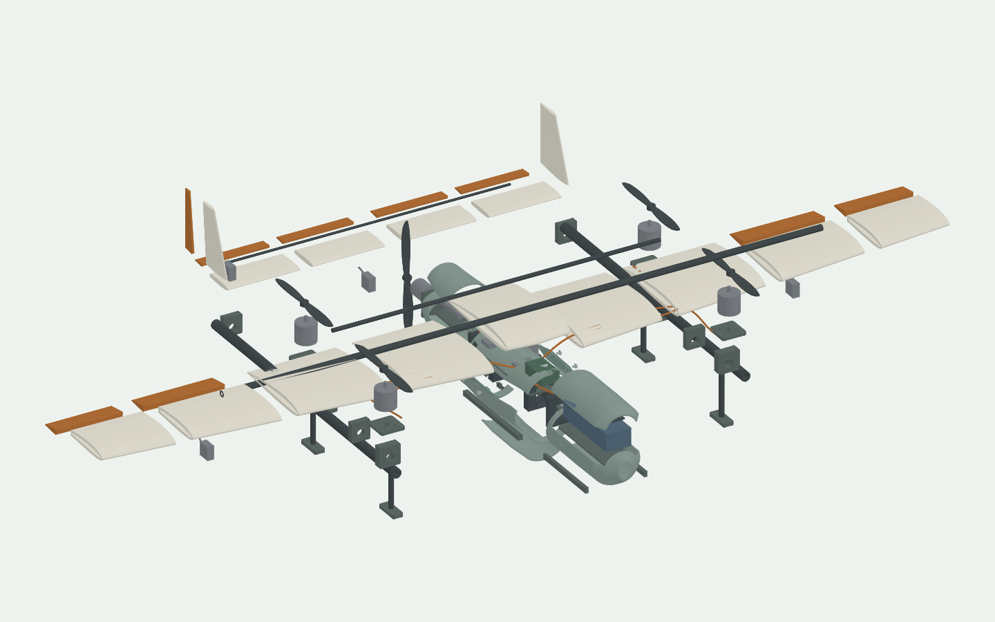
Explore the assembly, exploded view and components in 3D
Open full-window 3D referenceCompare the assembled and exploded views alongside the guide. Select Wiring to inspect the candidate harness routes. Toggle Show fairings to compare both successor configurations with the mounting shoes in place.
Connection checks
- Keyed fuselage rails and captive pins
- Measure the 0.15, 0.25 and 0.35 mm coupon pairs first. At both fuselage seams, seat each rail against its shoulder, check the replaceable detent and engage its independent captive pin. Record gap, rocking and retention after repeated assembly.
- Removable nose and aft modules
- Check the seams at X174 and X356 mm with the battery disconnected. The nose tray travels with the nose, and the aft rails and ESC tray travel with the aft module. Disconnect the crossing leads and release their restraints before testing withdrawal and pin access.
- Wing, boom and propulsion hardpoints
- Dry-fit the spars, booms, lift supports, pusher firewall and skids into the internal frame. Check the actual engagement, panel alignment and fastener retention at each attachment before closing access panels.
- Removable wing-to-pod fairings
- Trial-fit the M2 screws, load washers and inserts on a spare matching crown before bonding the four anchor shoes. Measure clearance to the wing and roof, then check that each shell slides outboard after screw removal. Keep the shoes installed for both fairing-on and fairing-off observations.
- H-tail and aileron controls
- With every propeller removed, check servo mounting, hinge and horn retention, and free linkage travel for both ailerons, elevator and rudder. Keep wiring clear of the latch pins, moving linkages and rear pusher envelope.
Print and measure the seam coupons
- Why this matters
- The shoulder sets the seam position and the independent pin carries retention. The coupon ladder checks how the selected print process affects both.
- Where to look
- Match the marked spigot and receiver pairs on the coupon sheet. Keep the insertion axis and pin access visible while checking fit.
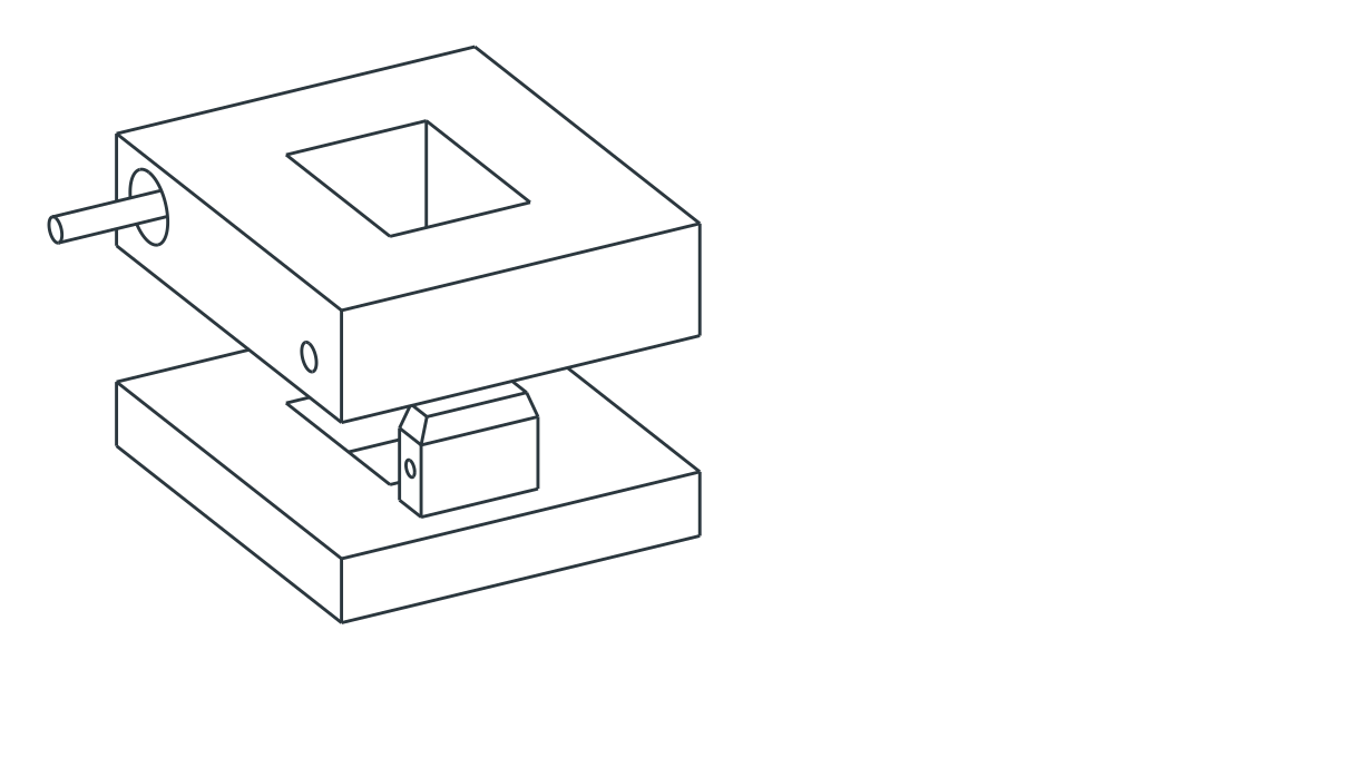
- Slice the 0.15, 0.25 and 0.35 mm clearance-per-side coupon ladder first on the Bambu Lab P1S with its 0.4 mm nozzle. Record the nozzle, filament and lot, slicer profile, orientation and any support or cleanup for each fit sample.
- Slide each keyed rail to its shoulder, check that the replaceable detent clicks at full seating, and verify the captive pin seats and stays retained. Check that partial engagement is visible and that deliberate release works without forcing the printed parts.
- Record gap, play, insertion and release behavior, and pin engagement before and after repeated assembly and review-approved load and environmental trials. Hold the airframe print if a coupon binds, rocks, cracks or loses retention.
Before you continue
Record gap, rocking, insertion and withdrawal effort, and pin engagement for each clearance before selecting a fit.
Show reference images for this step
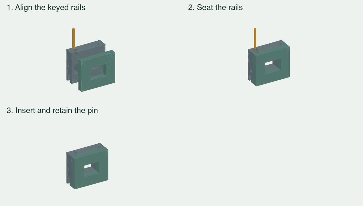
Dry-fit the fuselage and structural frame
- Why this matters
- The nose and aft interfaces locate the shell modules and give access to their own trays and harness branches.
- Where to look
- Find the two fuselage seams and their pin locations in the exploded view. Identify which tray and rails travel with each removable module.
- Inspect the printed shoulders and rail carriers. Dry-fit the nose and aft shell to the center at X174 and X356 mm. Check both pins independently after seating the shells.
- Trial-fit the spar, boom, lift mount supports, pusher firewall and skids on the internal frame. Check that motor, wing and landing loads have reviewed paths into the structure. Check that the frame can be inspected and the shells can be removed without disturbing it.
- Set the battery on its tray with the axial stop and both straps. With the battery unplugged, check connector access, lead bend radius and clearance through both seams. Record part masses, actual engagement and observed interference.
- Use the coupon for the isolated rail and pin sequence. The nose tray and battery move with the nose, and the aft rails and ESC tray move with the aft module. Disconnect and free the harness across each seam before checking installed travel and clip access.
Before you continue
Both pins engage independently at full seating, and the actual harness can be disconnected before moving either module.
Fit and remove the wing-to-pod fairings
- Why this matters
- Removable shoulders allow a matched comparison of the installed fairings and the same crown with its anchor shoes exposed.
- Where to look
- Look beneath the wing root at the port and starboard crown shoulders. The screws and load washers come out before each shell moves outboard.
- Use a separate 0.2.0 crown for the fairing study. Dry-fit both PETG anchor shoes and the LW-PLA shell on each side. Nominal shell ray samples show 1.077 mm to the wing and 1.474 mm to the roof. Measure the actual clearances and access with the assembly unpowered.
- Dry-fit the actual M2 screw, load washer and insert stack on a spare matching crown. The four shoes sit at X246 and X296 mm with a nominal 0.45 mm bond gap. The Ø3.2 × 4.4 mm insert bore is a sizing witness. Confirm insert retention and actual screw length before bonding the shoes.
- Remove the four M2 screw and washer sets and pull each shell straight outboard. Leave the four shoes installed in both successor configurations. Record A with both fairings off and B with both fairings on. Record the configuration, revision and setup for each observation. Keep the original 0.1.0 build as a separate control.
- Use independent retention or guarded containment on the bench. Review fit and loaded retention before moving to a powered test. Record actual section mass and any temperature or vibration differences.
Before you continue
Check insert depth, bond gap, measured clearances and attachment retention. Record complete fairing-on and fairing-off masses.
Fit the wing, tail and flight controls
- Why this matters
- Wing seating, spar engagement and retained linkages keep the control surfaces aligned under load.
- Where to look
- Follow the spars through the wing roots and the servo leads past the removable fuselage modules. Inspect the H-tail linkages and rear pusher envelope.
- Dry-fit the wing panels and H-tail. Inspect spar engagement, alignment, panel seats and retained fasteners before closing access panels.
- Fit the four HS-65MG servos to the port and starboard ailerons, elevator and starboard rudder. Check mechanical neutral, hinge and linkage retention, and free movement through the approved bench travel with each surface moved individually and together.
- Mock up the routed servo leads and check service disconnects, abrasion protection and clearance from moving linkages, latch pins and the pusher disc.
Before you continue
Confirm full free travel, matching panel alignment and clearance to the fixed fairing shoes, wiring and pusher disc.
Fit the four lift motors and rear pusher
- Why this matters
- The lift stations and rear pusher use different mounts and have separate load and cooling paths.
- Where to look
- Identify all four lift adapters and the cruise mount before choosing screws or securing the ESC leads.
- Trial-fit the four EMAX lift motors and the BadAss cruise motor to their respective adapters. Confirm the delivered mounting patterns, screw engagement, winding clearance, adapter stack and access for inspection. Keep propellers off for installation and electrical setup.
- Identify the two standard and two reverse APC 7 × 4 lift propellers and the separate APC 8 × 6 reverse pusher. With power disconnected, use a clearance gauge or hand sweep to check all five discs against the airframe, wing, tail, skids and wiring. Remove the propellers again before powering the controller.
- Secure the lift and cruise ESCs with airflow and strain relief. Confirm that phase wiring cannot reach the propeller envelopes or be pinched by a shell or hatch.
Before you continue
Verify delivered mounting patterns, screw depth and phase lead restraints with all propellers removed.
Route signals, power and sensors
- Why this matters
- Separate power and signal paths make isolation and inspection possible during service.
- Where to look
- Use the wiring worksheet and 3D harness traces to identify the power branches, service disconnects and controller outputs.
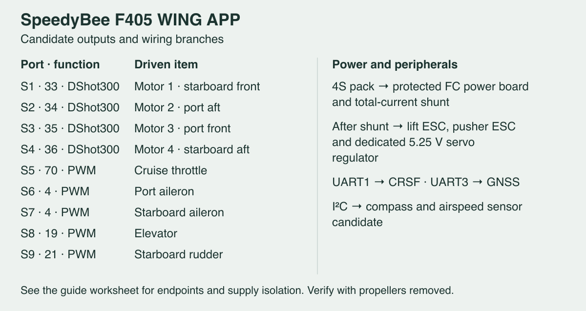
- S1 Motor 1 · starboard front (DShot300, function 33) · S2 Motor 2 · port aft (DShot300, function 34) · S3 Motor 3 · port front (DShot300, function 35)
- S4 Motor 4 · starboard aft (DShot300, function 36) · S5 Cruise throttle (PWM, function 70) · S6 Port aileron (PWM, function 4)
- S7 Starboard aileron (PWM, function 4) · S8 Elevator (PWM, function 19) · S9 Starboard rudder (PWM, function 21)
- Connect CRSF to UART1 and GNSS to UART3. Route the compass and pitot differential pressure sensor to I²C. Keep the compass and receiver antennas clear of high-current wiring and carbon where practical. Reserve an unobstructed pitot location and check tubing for leaks and kinks.
- Feed the servo breakout with the external Castle BEC at the documented 5.25 V target and maintain a common signal ground. Isolate the cruise ESC’s red BEC positive and the controller’s servo BEC positive from the external servo rail. Verify controller and peripheral power separately against their documented voltage and load limits.
- Inspect polarity, insulation, branch protection and the current measurement path. Record connector types and wire sizes. Hold combined motor operation until the battery leads, mating connector and branch harness have a reviewed load budget.
Before you continue
Record terminal assignments, connector types, wire sizes and measured clearances through both removable seams.
Commission the controller with propellers removed
- Why this matters
- Individual channel checks establish the motor map, control direction and isolation before the propulsion system carries a load.
- Where to look
- Use the bench output worksheet, flight controller and the separate lift and cruise branches.
- Restrain the airframe, remove all five propellers and use a current-limited source for first power. Confirm rail voltages, current draw and absence of backfeed before connecting loads. Check both BEC feed connections and monitor rail behavior while moving all control surfaces.
- Record the ArduPilot build and calibration. Verify sensor orientation and response, CRSF link and loss behavior, low-power indications, throttle cut and disarm, and correct control movement with adequate clearance. Test GNSS and compass separately from the pitot zero and response checks.
- Verify the four lift motor positions and directions one output at a time. Confirm cruise direction independently and confirm all five motors stop on command. Save the output map, parameter export and test log.
Before you continue
Confirm rail voltages, stop behavior and individual motor direction with all propellers off. Save the parameter export.
Run guarded propulsion tests
- Why this matters
- A guarded single-branch fixture lets the builder measure the actual motor, propeller and electrical combination.
- Where to look
- Use the reviewed stand, guard, remote disconnect and measurement instruments before fitting a propeller.
- After fixture and hardware review, fit one matched motor, propeller and retainer on a guarded stand. Use remote power isolation. Verify propeller orientation, thrust direction and RPM for each handed lift configuration and the cruise pusher.
- Log thrust, RPM, battery voltage and sag, branch current and temperatures at the motor, ESC, wiring and connectors. Stop on vibration, loosened retention, abnormal heating, desynchronization or electrical limits. Use the exact pack state and test duration in the record.
- Compare measured results with the approved component and power-path limits. Test simultaneous loads only on a qualified, guarded power path. Reinspect hardpoints, pins and wiring after testing.
Before you continue
Record measured current, thrust, temperatures and hardpoint condition before any integrated powered test.
Review the evidence before hover and transition
- Why this matters
- Measured retention, load, balance and control evidence establishes whether this exact article can proceed to supervised testing.
- Where to look
- Use the installed battery datum and lift-rotor center, then inspect the fairings, pins, harness restraints and fixed-wing control surfaces.
- Record measured all-up mass and balance with the pack secured, review the relationship between the center of gravity and lift rotor center, and confirm structural retention, control limits, radio range and failsafe behavior for this exact configuration.
- Hold hover and transition pending review of measured lift reserve, current and thermal margins, installed airspeed sensing, both transition directions and abort behavior. Exercise the mode sequence and failure handling in simulation or a controlled bench setup first.
- Use a separately reviewed field plan to establish controlled hover and landing before evaluating either transition. Record flight results only after the corresponding physical test.
Before you continue
Record reviewed bench results and keep hover, landing and both transition directions as separate physical test records.
Checks to record
- Record the exact part hashes, material lot, saved P1S profile, coupon gaps and loaded seam retention.
- Inspect the aft pod rim and crown plus both optional fairing edges during dry-fit. The saved aft-pod outer wall ends at Z64.2 mm against a CAD maximum of Z64.643 mm because two isolated rim tips are narrower than the extrusion line. The removable joint lies away from these tips.
- Record the actual M2 insert engagement and crown bond, both fairing masses, installed clearance and retention. Keep the baseline and fairing-off controls distinct.
- Inspect complete mass and balance, loaded control direction and throws, propeller clearance, radio range, failsafe, current and temperatures.
- Record reviewed hover, both transitions and landing independently after the exact physical article passes its bench gates.