3D printed RC aircraft · Revision R2-S2
Raven Plank R2-S2
A 650 mm rear-pusher flying wing for bench review, with a keyed pod splice, adjustable battery restraint and revised elevon servo mounts.
Bench review · Physical fit, structural strength, balance and flight remain unverified.
The latest bench CAD is shown in the preview. The build guide and member kit use R2-S2.
- Wingspan
- 650 mm
- Wing section
- Hollow airfoil
- Configuration
- Rear-pusher flying wing
Illustrated guide, bill of materials, STLs and Bambu Studio projects in one ZIP.
Loading the 3D view…
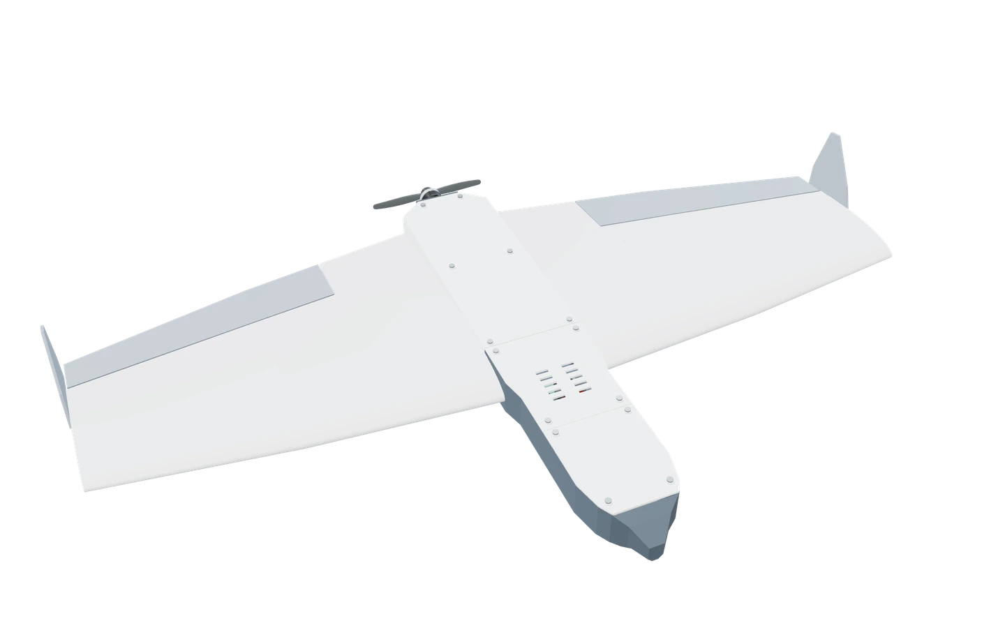
Exploded view inventoryR2-S3 bench preview
- Airframe
- All 30 named airframe solids, including the keyed pod overlap, separate avionics tray and carbon spars.
- Fasteners and linkages
- 90 nominal screw, nut and washer references, including four pod clamp stations, four avionics tray fasteners and the wing servo mounts.
- Electronics and wiring
- Battery, motor and propeller, receiver, ESC, elevon servos and schematic wiring references.
- Items to check in the build guide
- Fit the elevon horns and pushrod hardware to the actual installation, and check screw engagement, wiring clearance and retention. Select R2-S2 build reference for the released kit and guide.
A flying wing with no separate tail
- Airframe
- Four hollow printed wing panels slide onto two continuous carbon tubes. The center pod supports the wing roots, the tip fins stand at the ends of the wing, and the rear propeller leaves the nose free for the battery and electronics.
- How it’s controlled
- The two trailing-edge flaps are elevons: they move together for pitch and in opposite directions for roll. That makes this a different control layout from the Scout and Trainer, which use separate surfaces on a tail.
- Who it’s for
- A bench project for RC builders exploring tailless layouts, or a design lab comparing the different jobs two servos do in a flying wing and a conventional trainer.
- Flight targets
- No range, speed or altitude targets are published for this revision.
Print files
The member build kit contains the STLs and print profiles for revision R2-S2.
Print setup
- Use the six editable Bambu Lab P1S projects with a 0.4 mm nozzle, Textured PEI and 0.20 mm layers. Supports are off in the supplied projects. Slice and inspect each plate before printing.
- Bambu PLA Aero uses one wall and 5% gyroid on the flat and inner-wing projects, and 3% gyroid on the outer-wing and elevon project. Keep the saved 8 mm outer brim on the wing and elevon plates.
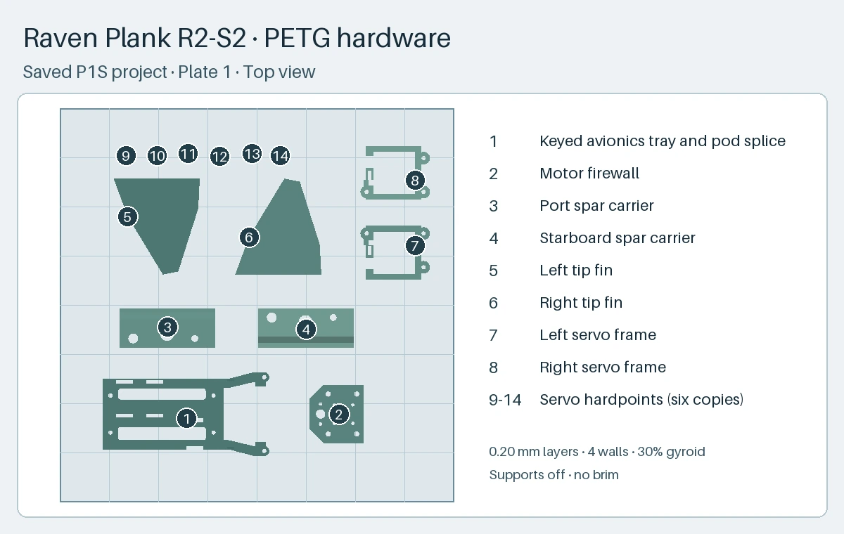
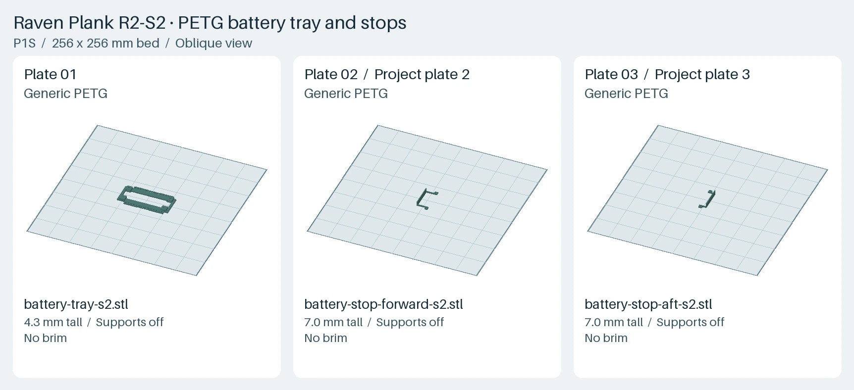
- Generic PETG uses four walls and 30% gyroid. The hardware project includes the keyed avionics tray, both revised servo frames and all six identical hardpoints. The battery project contains the tray and both stops.
- Start with the two bore coupons, one in each material. Check both carbon tube fits before printing the airframe. The coupons are separate from the 28 installed printed pieces.
View the 23 printed parts
Images show the exported meshes for this revision. Each part is shown at its own scale.
| Part and STL filename | Image | Quantity | Material |
|---|---|---|---|
Nose podparts/pod-nose.stl | 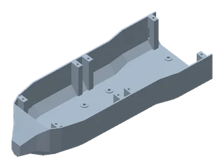 | 1 | Bambu PLA Aero |
Aft podparts/pod-center.stl | 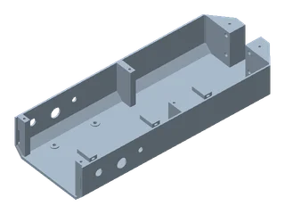 | 1 | Bambu PLA Aero |
Battery hatchparts/battery-hatch.stl | 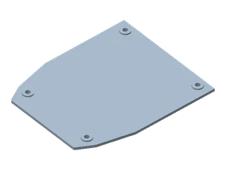 | 1 | Bambu PLA Aero |
Avionics hatchparts/electronics-hatch.stl | 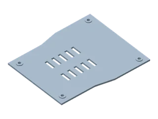 | 1 | Bambu PLA Aero |
Aft service hatchparts/service-hatch.stl | 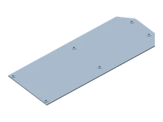 | 1 | Bambu PLA Aero |
Port spar carrierparts/spar-carrier-port.stl | 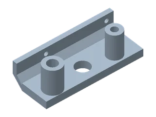 | 1 | Generic PETG |
Starboard spar carrierparts/spar-carrier-starboard.stl | 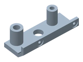 | 1 | Generic PETG |
Motor firewallparts/motor-firewall.stl | 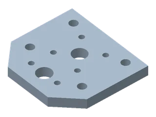 | 1 | Generic PETG |
Right outer wingparts/wing-tip-R.stl | 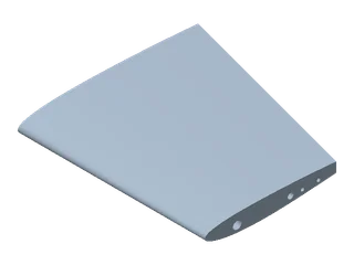 | 1 | Bambu PLA Aero |
Left outer wingparts/wing-tip-L.stl | 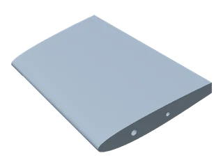 | 1 | Bambu PLA Aero |
Right elevonparts/elevon-R.stl | 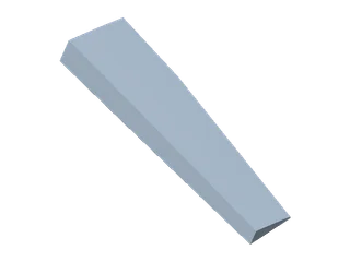 | 1 | Bambu PLA Aero |
Left elevonparts/elevon-L.stl | 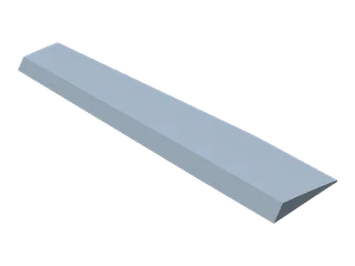 | 1 | Bambu PLA Aero |
Right tip finparts/tip-fin-R.stl | 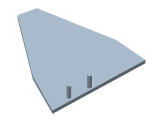 | 1 | Generic PETG |
Left tip finparts/tip-fin-L.stl | 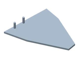 | 1 | Generic PETG |
Battery tray with strap slotsparts/battery-tray-s2.stl | 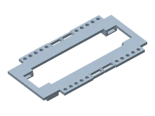 | 1 | Generic PETG |
Forward battery stopparts/battery-stop-forward-s2.stl | 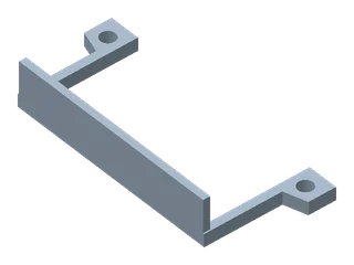 | 1 | Generic PETG |
Aft battery stopparts/battery-stop-aft-s2.stl | 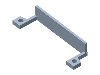 | 1 | Generic PETG |
Right inner wingparts/wing-root-R-s2.stl | 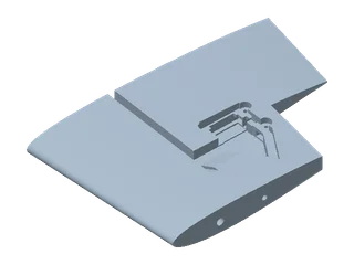 | 1 | Bambu PLA Aero |
Right servo frameparts/servo-frame-R-s2.stl | 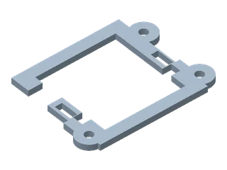 | 1 | Generic PETG |
Servo hardpointparts/servo-hardpoint-R1-s2.stl | 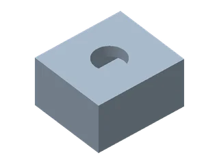 | 6 | Generic PETG |
Left inner wingparts/wing-root-L-s2.stl | 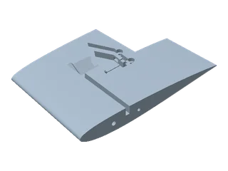 | 1 | Bambu PLA Aero |
Left servo frameparts/servo-frame-L-s2.stl | 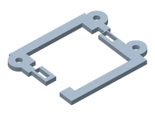 | 1 | Generic PETG |
Keyed avionics tray and pod spliceparts/electronics-tray-keyed-splice.stl | 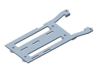 | 1 | Generic PETG |
Workshop tools
Use your existing workshop equipment where suitable. The reference printer and these tools are budgeted separately.
- Bench tools: Straight assembly jig, calipers, scale and balance fixture, multimeter, and guarded independent propulsion stand for current, RPM, temperature and vibration checks. Select fixtures and instruments for the exact build.
Bill of materials
Aircraft parts, assembly supplies, and radio and charging gear for revision R2-S2.
Printed-part images show the exported meshes. Hardware and supply drawings help identify items. Images are not to scale.
Download BOM (CSV)Scroll each table sideways to see specifications and supplier links.
Printed parts and filament28 items
| Item | Image | Qty | Price (USD) and stock | Specification & sourcing |
|---|---|---|---|---|
| Nose pod | | 1 | Print from the kit | Bambu PLA Aero · parts/pod-nose.stl |
| Aft pod | | 1 | Print from the kit | Bambu PLA Aero · parts/pod-center.stl |
| Battery hatch | | 1 | Print from the kit | Bambu PLA Aero · parts/battery-hatch.stl |
| Avionics hatch | | 1 | Print from the kit | Bambu PLA Aero · parts/electronics-hatch.stl |
| Aft service hatch | | 1 | Print from the kit | Bambu PLA Aero · parts/service-hatch.stl |
| Right outer wing | | 1 | Print from the kit | Bambu PLA Aero · parts/wing-tip-R.stl |
| Left outer wing | | 1 | Print from the kit | Bambu PLA Aero · parts/wing-tip-L.stl |
| Right elevon | | 1 | Print from the kit | Bambu PLA Aero · parts/elevon-R.stl |
| Left elevon | | 1 | Print from the kit | Bambu PLA Aero · parts/elevon-L.stl |
| Right inner wing | | 1 | Print from the kit | Bambu PLA Aero · parts/wing-root-R-s2.stl |
| Left inner wing | | 1 | Print from the kit | Bambu PLA Aero · parts/wing-root-L-s2.stl |
| Port spar carrier | | 1 | Print from the kit | Generic PETG · parts/spar-carrier-port.stl |
| Starboard spar carrier | | 1 | Print from the kit | Generic PETG · parts/spar-carrier-starboard.stl |
| Motor firewall | | 1 | Print from the kit | Generic PETG · parts/motor-firewall.stl |
| Right tip fin | | 1 | Print from the kit | Generic PETG · parts/tip-fin-R.stl |
| Left tip fin | | 1 | Print from the kit | Generic PETG · parts/tip-fin-L.stl |
| Battery tray with strap slots | | 1 | Print from the kit | Generic PETG · parts/battery-tray-s2.stl |
| Forward battery stop | | 1 | Print from the kit | Generic PETG · parts/battery-stop-forward-s2.stl |
| Aft battery stop | | 1 | Print from the kit | Generic PETG · parts/battery-stop-aft-s2.stl |
| Right servo frame | | 1 | Print from the kit | Generic PETG · parts/servo-frame-R-s2.stl |
| Servo hardpoint | | 6 | Print from the kit | Generic PETG · parts/servo-hardpoint-R1-s2.stl |
| Left servo frame | | 1 | Print from the kit | Generic PETG · parts/servo-frame-L-s2.stl |
| Keyed avionics tray and pod splice | | 1 | Print from the kit | Generic PETG · parts/electronics-tray-keyed-splice.stl |
| Spar bore coupon · PLA Aero | 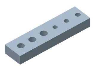 | 1 | Print from the kit | parts/bore-coupon-lw-pla.stl. Use the bore ladder to check both delivered tubes. Bench test piece. Does not go on the aircraft. |
| Spar bore coupon · PETG | 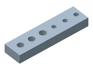 | 1 | Print from the kit | parts/bore-coupon-petg.stl. Use the bore ladder to check both delivered tubes. Bench test piece. Does not go on the aircraft. |
| Bambu PLA Aero | As needed | $5.99 221.937 g at $0.027/g $26.99 / 1000 g spool In stock Recheck stock · In stock at last check | Foaming PLA for the pod, hatches, wing panels and elevons. Check wall adhesion, finished mass and cap bridges on the first part. White 14102 with spool, 1 kg. Bambu lists this variant in stock. Estimate combines retained R2 prints with both revised R2-S2 wing roots, excluding fit coupons. | |
| PETG | As needed | $0.60 49.965 g at $0.012/g $11.99 / 1000 g spool In stock Recheck stock · In stock at last check | Generic PETG for the keyed splice, carriers, firewall, tip fins, revised battery parts, servo frames and hardpoints. Example unfilled 1.75 mm PETG. Confirm the material and settings on the fit coupon. Soleyin Basic PETG black, 1 kg. Seller publishes quantity for this variant. R2-S2 estimate covers the hardware plate and three battery parts, excluding fit coupons. | |
| Generic PLA | Optional | $0.012/g $11.99 / 1000 g spool In stock Recheck stock · In stock at last check | Optional regular PLA for fit-only pod or hardware trials. Use only for unpowered fit checks. Example 1.75 mm PLA for fit prints. Soleyin Ultra PLA, 1 kg. Seller publishes quantity. Optional unpowered fit-test material. |
Propulsion and onboard electronics10 items
| Item | Image | Qty | Price (USD) and stock | Specification & sourcing |
|---|---|---|---|---|
| EMAX ECO Micro 1407 brushless motor | 1 | $12.99 / motor In stock Recheck stock · In stock at last check | 3300 KV version with a 12 × 12 mm mounting pattern and M5 propeller adapter. Verify the installed motor and mounting screw engagement. Selected 3300 KV model is available to order on the US store. | |
| HQProp 4 × 2.5 two-blade propeller | 1 installed | $2.84 / four-prop pack In stock Recheck stock · In stock at last check | 101.6 mm swept diameter, 5 mm bore and 6 mm hub thickness. Select rotation and orientation for aft airflow. Check the full disk clearance. The four-pack includes clockwise and counterclockwise propellers. SKU 01AE17, gray two-blade 4 × 2.5, two CW and two CCW. Two packs listed. | |
| Hobbywing Skywalker 30A V2 Mini ESC | 1 | $21.50 / ESC In stock Recheck stock · In stock at last check | SKU 30205202. PWM throttle, 2–4S LiPo input and switched 5 V / 3 A BEC. Confirm cooling and servo-rail voltage with the actual harness. SKU 30205202. The seller marks this exact Mini variant available to order. | |
| Hitec HS-65MG analog servo | 2 | $35.99 / servo 2 × $35.99 = $71.98 In stock Recheck stock · In stock at last check | 23.6 × 11.6 × 24.0 mm case, 4.8–6.0 V, one servo for each elevon. Set the ER4 servo outputs to 50 Hz. Verify frame, lead and horn clearance. Hitec HS-65MG. Seller variant data lists 22 available for the two required servos. | |
| RadioMaster ER4 PWM receiver | 1 | $14.99 / receiver In stock Recheck stock · In stock at last check | 2.4 GHz ExpressLRS, four PWM outputs, 4.5–8.4 V supply, 30 × 15 × 5 mm body. CH1 left elevon, CH2 right elevon, CH3 ESC throttle and BEC. Seller marks SKU HP0157.RX-ER4 available to order. | |
| Tattu R-Line 5.0 850 mAh LiPo | 1 | $17.99 / battery In stock Recheck stock · In stock at last check | 3S, 11.1 V nominal, XT30U-F main connector, about 58 × 30 × 23 mm. Check the actual pack, leads, strap and stops for clearance under the hatch. SKU TA-RL5-150C-850-3S1P, 3S 150C with XT30U-F. Seller marks the exact battery available. | |
| Motor-approved propeller retention hardware | 1 set | Source to choose | Retention hardware for the motor’s M5 adapter and 6 mm propeller hub. Confirm the hardware in the exact motor package and check engagement. Confirm the exact M5 adapter hardware in the motor package before buying a separate set. | |
| PWM servo extensions | 2 | $0.89 / lead 2 × $0.89 = $1.78 In stock Recheck stock · In stock at last check | Budget 100 mm each with secured plugs. Confirm length, plug passage and connectors with the wing and pod dry-fitted. 100 mm JR-compatible example. Confirm the plugs and routing on the actual installation. SEC-2002-100, 100 mm JR-compatible leads. Seller lists three available. | |
| Motor-phase extensions | 3 conductors | Source to choose | Three insulated ESC-to-motor conductors. Verify the installed route past the S2 splice, carriers and spars before cutting. Measure installed lengths and select gauge, joins, insulation and strain relief for the actual harness. Measure the installed path and select conductor gauge and length during dry fit. | |
| Mating XT30 connector | 1 as needed | $1.17 / connector In stock Recheck stock · In stock at last check | Mates with the pack’s XT30U-F main lead. Verify the actual ESC input, pack mating and polarity. Amass XT30U-M cable-mount plug for the pack’s XT30U-F. Confirm polarity and whether the ESC already has the matching plug. Selected Amass XT30U-M in yellow. Needed only if the ESC has no matching plug. |
Airframe stock and linkages4 items
| Item | Image | Qty | Price (USD) and stock | Specification & sourcing |
|---|---|---|---|---|
| Main carbon tube | 1 | $4.65 / 1 m tube In stock Recheck stock · In stock at last check | 6 mm OD × 4 mm ID × 640 mm, continuous across the pod and both wing joints. Measure the delivered tube and check the bore coupon before cutting. Buy 1,000 mm stock and trim it to 640 mm after checking the bore fit. The 1,000 mm option of the 6 × 4 mm tube is in stock. Check the bore before trimming to 640 mm. | |
| Rear carbon tube | 1 | $5.72 / 1 m tube In stock Recheck stock · In stock at last check | 4 mm OD × 2 mm ID × 630 mm, continuous across the pod and both wing joints. Measure the delivered tube and check the bore coupon before cutting. Buy 1,000 mm stock and trim it to 630 mm after checking the bore fit. SKU CFT421, 4 × 2 × 1,000 mm pultruded tube. Nine listed. Check the bore before trimming to 630 mm. | |
| Elevon control horns and pushrods | 2 sets | Source to choose | One mechanically retained linkage per elevon. Include the servo horn and suitable clevises or equivalent retainers. Select the exact hardware and set lengths after dry fit. Select two mechanically retained linkages after measuring the installed servo and elevon geometry. | |
| Flexible hinge tape | 2 hinge lines | $5.95 / roll In stock Recheck stock · In stock at last check | Across the upper seam of each elevon. DU-BRO #916 is one option. Check adhesion, retention and free elevon travel on both printed surfaces. DU-BRO 916, one roll. Seller lists in stock. Check adhesion and free travel with the selected material. |
Fasteners and assembly supplies22 items
| Item | Image | Qty | Price (USD) and stock | Specification & sourcing |
|---|---|---|---|---|
| Battery straps | 2 | Source to choose | Flexible strap to suit the tray slots. CAD fit uses 6 mm wide × 1 mm thick. Select after measuring the tray slots, pack and buckle clearance under the actual hatch. Select two straps after checking the 6 mm tray slots and buckle clearance. | |
| Servo-to-frame straps | 2 | Source to choose | One flexible strap per servo. The modeled passage allows up to 5.2 mm width and about 1 mm thickness. Check the frame slots and actual servo case before ordering or cutting straps. Select straps after measuring the actual 5.2 mm frame passages and servo cases. | |
| ESC and receiver retainers | 2 fitted sets | Source to choose | One independent restraint per case. Size after a dry fit on the keyed splice tray and check both lids, cooling and wiring. Measure both cases and lid clearances during dry fit. | |
| Nose splice screws | 4 | $0.11 / screw 4 × $0.11 = $0.44 In stock · Required quantity unconfirmed Recheck stock · In stock at last check | M2.5 machine screws, 90° countersunk. The nominal nose candidate is 14 mm. Measure the grip and check flush seating and full locknut engagement with a washer fitted. SF2.5X14TXSS, 90° countersunk M2.5 × 14 mm nominal candidate. Seller lists in stock without a unit count. Check seating and grip. | |
| Forward carrier and splice screws | 2 | Source to choose | M2.5 machine screws, 90° countersunk. Select length after measuring the grip with the 2.1 mm splice tab installed. Use the supplier family to select the measured length. Verify flush heads, clearance and full locknut engagement. Use the supplier family to select the 90° countersunk screw length after measuring the installed splice tab and carrier. | |
| Rear spar carrier screws | 2 | $0.09 / screw 2 × $0.09 = $0.18 In stock · Required quantity unconfirmed Recheck stock · In stock at last check | M2.5 machine screws, 90° countersunk. The retained rear stations use the original 12 mm candidate. Check actual grip, flush seating and locknut engagement. SF2.5X12TXSS, 90° countersunk M2.5 × 12 mm nominal candidate. Seller lists in stock without a unit count. Check seating and grip. | |
| M2.5 low-profile flat washers | 8 | $0.07 / washer 8 × $0.07 = $0.56 In stock · Required quantity unconfirmed Recheck stock · In stock at last check | One at each of the six splice stations and each of the two rear carrier stations. WF2.5X5CLZ, DIN 433, 5 mm outside diameter. Listing marks in stock and does not publish a unit count. | |
| M2.5 locknuts | 8 | $0.17 / nut 8 × $0.17 = $1.36 In stock · Required quantity unconfirmed Recheck stock · In stock at last check | One above each splice and carrier washer. Verify full engagement of every locking element. NN2.5SS M2.5 × 0.45 DIN 985. Listing marks in stock and does not publish a unit count. | |
| Battery tray floor screws | 4 | $0.23 / screw 4 × $0.23 = $0.92 In stock Recheck stock · In stock at last check | M2.5 × 6 mm fully threaded, 90° countersunk machine screws. Verify the blind tip clearance and keep the pocket roof intact. M2.5 × 6 mm fully threaded DIN 7991. Seller lists 194 units. Check the blind pocket and tip clearance. | |
| Battery tray thin square nuts | 4 | $0.20 / nut 4 × $0.20 = $0.80 In stock · Required quantity unconfirmed Recheck stock · In stock at last check | M2.5 DIN 562 with the modeled 5 × 5 × 1.6 mm envelope. Slide the nuts into their pockets from the tray center opening. NSQ2.5JAMSS, DIN 562 thin M2.5. Listing marks in stock and does not publish a unit count. Check pocket dimensions. | |
| Battery stop screws | 4 | $0.08 / screw 4 × $0.08 = $0.32 In stock · Required quantity unconfirmed Recheck stock · In stock at last check | M2 × 6 mm pan- or socket-head machine screw candidates. Measure length under the head and confirm the grip. MSP2X6SS, M2 × 6 mm DIN 7985 pan head. Listing marks in stock and does not publish a unit count. Confirm grip length. | |
| Battery stop nuts | 4 | $0.12 / nut 4 × $0.12 = $0.48 In stock · Required quantity unconfirmed Recheck stock · In stock at last check | Low-profile M2 hex nuts. Verify pocket fit, full thread engagement and clearance to the pack. 2CNFJ0Z, M2 × 0.4 DIN 439 thin hex nut. Listing marks in stock and does not publish a unit count. Check pocket fit. | |
| Servo frame screws | 6 | $0.08 / screw 6 × $0.08 = $0.48 In stock · Required quantity unconfirmed Recheck stock · In stock at last check | M2.5 × 8 mm pan-head machine screw candidates. Check engagement and clearance with the actual frame, hardpoint and servo. MSP2.5X8SS, M2.5 × 8 mm DIN 7985 pan head. Listing marks in stock and does not publish a unit count. Confirm engagement and clearance. | |
| Servo hardpoint square nuts | 6 | Source to choose | M2.5 with a modeled 5 × 5 × 2 mm square envelope, one per keyed hardpoint. Verify the actual nut seats flush in the block. The battery-floor thin nuts have a separate specification. Source and measure the actual servo nuts before ordering in quantity. Source and measure an M2.5 square nut that fits the 5 × 5 × 2 mm envelope before ordering. The thinner DIN 562 battery-floor nut has a separate role. | |
| Removable metal-thread retention | As fitted | Source to choose | Select a removable method for the battery tray and stop fasteners and verify compatibility with the nearby PETG and pack. Choose the method after checking the screw materials, PETG clearance and pack handling. | |
| Hatch screws | 14 | $4.61 / 100-screw pack In stock Recheck stock · In stock at last check | M2.5 × 8 mm plastic thread-forming screws. Four for the battery hatch, four for the avionics hatch and six for the aft hatch. Try the actual screw in a printed 2 mm pilot before installation. Pan-head Plastite example. Verify pilot fit and head clearance before installing. Metric BVSB2008ITZ, M2.5 × 8 mm plastic thread-forming screw, 100 per pack. Seller lists the pack in stock. Verify pilot and head fit. | |
| Firewall bolts | 4 | $0.16 / bolt 4 × $0.16 = $0.64 In stock Recheck stock · In stock at last check | Start with M3 × 25 mm bolts. Insert from aft through the firewall and check grip length with the washers and locknut fitted. Socket-head M3 × 25 mm example. Check head and tool access. MSH030CF025AL, M3 × 25 mm class 12.9 DIN 912 socket-head screw. Seller lists 1,158 units. Verify thread engagement with the installed stack. | |
| M3 flat washers | 8 | $0.01 / washer 8 × $0.01 = $0.08 In stock · Required quantity unconfirmed Recheck stock · In stock at last check | Fit one washer on each side of each firewall bolt. M3SFW10PL, single class 10 flat washer. Selected single-piece variant shows available and does not publish a quantity. | |
| M3 locknuts | 4 | $0.09 / nut 4 × $0.09 = $0.36 In stock Recheck stock · In stock at last check | Fit one locknut inside the pod at each firewall bolt. M3 × 0.5 class 8 zinc nylon locknut. Seller lists 194 units. | |
| Motor mounting screws | 4 | Source to choose | M2 screws for the 12 × 12 mm motor pattern. Choose length for the installed firewall and motor. Measure usable thread depth, rotor clearance and screw penetration before selecting the length. Measure thread depth, firewall stack and rotor clearance to select the M2 length. | |
| Insulation and strain relief | As needed | Source to choose | Insulate and restrain phase joins, battery wiring and servo extension plugs. Size the insulation and restraints for the installed wires and plugs. Size both items for the installed wiring length and connector geometry. | |
| Structural adhesive | 1 set | Source to choose | Suitable for the actual carbon, PETG and PLA Aero substrates. Test adhesion on scrap printed with the same filament and settings before bonding the airframe. Select a suitable material after bonding tests on the actual carbon, PETG and PLA Aero samples. |
Radio and charging gear4 items
| Item | Image | Qty | Price (USD) and stock | Specification & sourcing |
|---|---|---|---|---|
| RadioMaster Pocket transmitter | 1 | $71.50 / transmitter In stock Recheck stock · In stock at last check | Internal 2.4 GHz ExpressLRS variant with EdgeTX. Use the same firmware major version and regulatory domain as the ER4. US link selects the ELRS FCC version. Choose ELRS LBT where required and match the receiver’s regulatory domain. HP0157.0054-M2, Charcoal, internal ELRS with FCC firmware. Seller marks the exact variant available. Cells are separate. | |
| Pocket transmitter cells | 2 | $11.99 / two-cell pack In stock Recheck stock · In stock at last check | Pocket-compatible 18650 cells. RadioMaster lists a 3.7 V, 3200 mAh pair. The transmitter is supplied without cells. One retailer pack supplies both 3200 mAh cells. HP0157.18650-3200, 3.7 V 3,200 mAh. One in-stock retail pack supplies both cells. | |
| 3S LiPo balance charger | 1 | $59.99 / charger In stock Recheck stock · In stock at last check | 3S LiPo balance mode with matching power and balance leads and charger supply. The Hitec RDX1 Mini #44295 supports 3S LiPo balance charging. Verify the pack’s balance plug and use the pack maker’s charge settings. HRC44295 RDX1 Mini. The exact charger is in stock and has a built-in XT60 output. | |
| XT60-to-XT30 charge adapter | 1 if the charger output is XT60 | $10.99 / adapter In stock Recheck stock · In stock at last check | Hitec #44185 connects an XT60 charger output to the flight pack’s XT30 main lead. Connect the pack’s separate balance lead to the matching balance port. Check connector mating and polarity on your charger and pack before connecting. Hitec 44185, in stock. Included in the estimate with the listed XT60-output charger. |
Build guide
Bench-fit guide for the 650 mm Raven Plank R2-S2. This revision uses a keyed pod splice, a bolted battery tray with adjustable stops, and revised elevon servo mounts. Keep the propeller off and the pack disconnected during assembly. Physical fit, structural capacity and flight remain unverified.
Bambu Lab P1S, 0.4 mm nozzle, Textured PEI and 0.20 mm layers. Use the supplied R2-S2 project placements and material-specific settings. Review the print inventory and bill of materials before starting. Use the 3D assembly reference to find parts on the aircraft. The plate images show how parts sit on the printer bed.
Inspect the nose, powertrain and equipment bay in 3D. The viewer uses nominal hardware references. Check the actual wiring, linkages and fit during assembly.
Connection checks
- Nose and aft pod
- Seat both shoulders by hand on a flat fixture. The keyed tray and carrier feet should seat before you tighten the screws. Recheck the seam and both spar bores after tightening.
- Wing roots, panel splits and tip fins
- Slide both continuous spars through the dry assembly. Check full root seating, clear servo leads, and free elevon travel. The tube bores and fin pins locate these parts. Confirm the bonded joints provide retention before assessing the completed wing.
- Hatches and equipment
- Close each cover over the retained equipment and inspect the leads at the seam and hatch edges. Verify the servo case straps, frame screws, battery straps and stops separately.
Check the parts and print the fit coupons
- Why this matters
- Check print fit and bore size before using material on the full airframe.
- Where to look
- The left and right inner wings come from the S2 project. The outer wings and elevons carry forward from R2.
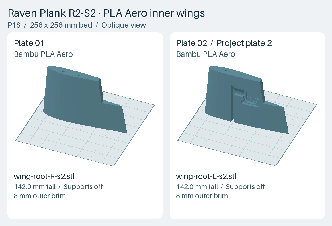
- Use the R2-S2 inner wing panels, servo frames, six keyed hardpoints, battery tray and both end stops. Use one PETG R2-S1 keyed splice, either the existing matching print or the copy supplied here. Keep the original short seam doublers, stock avionics tray, stock battery tray and stock servo frames out of this assembly.
- Print one bore coupon in PLA Aero and one in PETG. Measure both carbon tubes and check the 6.4 and 4.4 mm nominal bores on the coupons before committing to the airframe. Check spare material for bonding, and check hatch screw fit in a spare printed pilot.
- Use Bambu PLA Aero for the flat and wing projects. The flat parts and inner panels use one wall and 5% gyroid. The retained outer wings and elevons use one wall and 3% gyroid. Keep the 8 mm outer brim on the span-up wing and elevon plates.
- Use Generic PETG, four walls and 30% gyroid, for the battery parts, the structural and servo hardware plate, and the PETG coupon. Preview each saved plate in Bambu Studio and verify the spool, part count and placement. Regular PLA prototypes serve as fit samples only.
Before you continue
The real tubes pass through the selected coupon bores without forcing them or leaving excessive play.
Join the pod with the keyed splice
- Why this matters
- The keyed tray bridges the pod seam and shares the two forward carrier fasteners.
- Where to look
- Look into the open pod from above for the sockets and inward-facing carrier tabs. The screws enter from the belly.
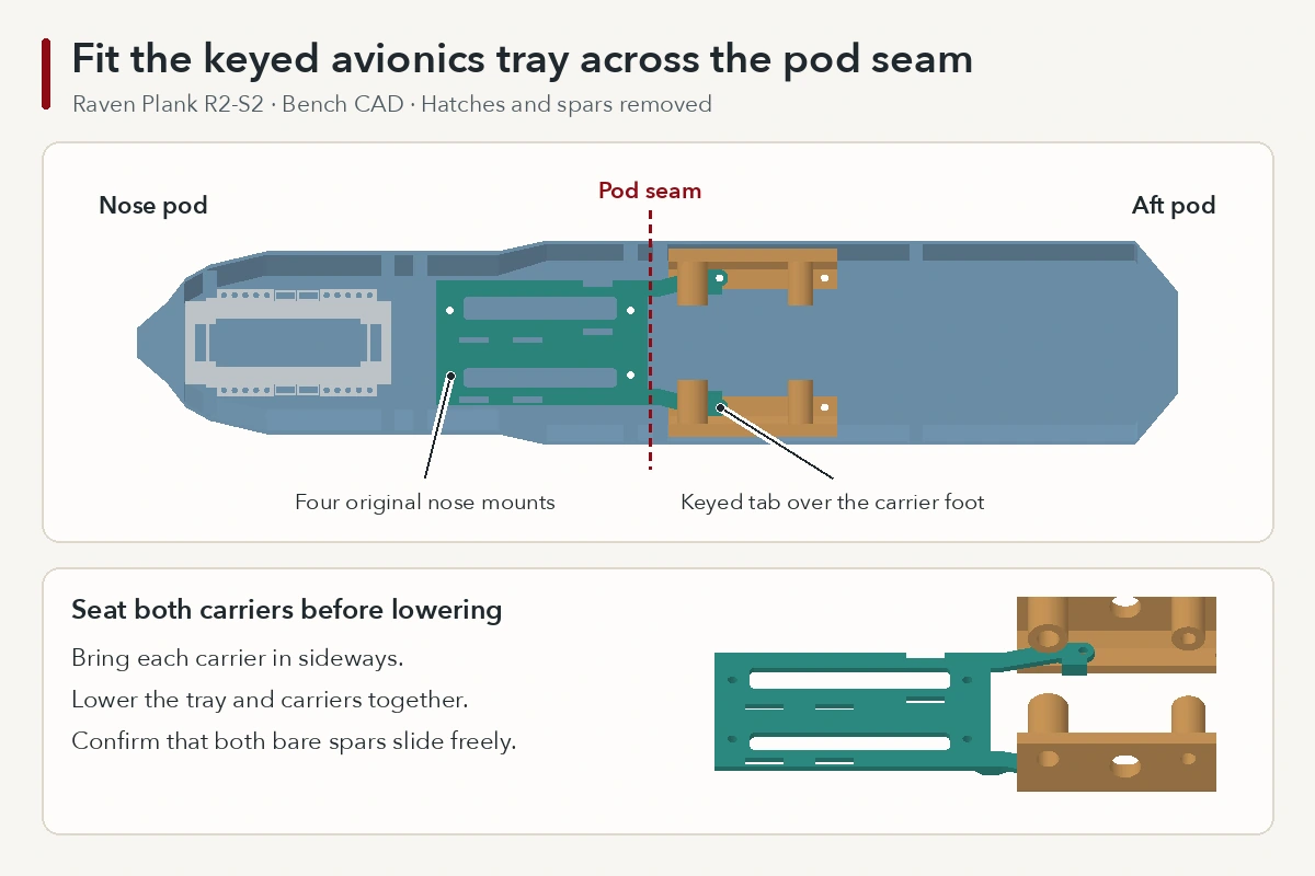
- Inspect the bare nose and aft pod for warping, cracks or lifted layers at the floor pads. Align the two shells on a straight fixture with hatches, motor, battery and spars out. The seam should close without screw pressure.
- Outside the pod, slide each carrier foot sideways under its splice tab with the locating lip facing inward. Lower both carriers and the tray into the open pod together. Seat all four nose sockets, both tabs and both carrier feet. Check the shell seam, wing-root faces and wiring lane.
- Fit four 90° countersunk M2.5 screws from the nose belly and two through the forward carrier stations. Try the nominal 14 mm nose candidates against the actual grip. The tabs add 2.1 mm of grip at the forward carrier stations. Select those two lengths by measurement. Fit a washer and locknut above each of the six stations.
- Retain the two separate rear carrier screws at the original stations. Check their grip and fit a washer and locknut at each. Confirm the eight heads sit flush, all locking elements engage, and nothing projects into equipment or wiring. Slide both bare spars through the carriers to check for binding. Stop if a fastener shifts a carrier or distorts the seam.
Before you continue
The seam is flush before tightening. All eight heads seat flush and both bare spars pass freely.
Fit the tray, end stops and battery restraints
- Why this matters
- Two straps secure the pack vertically and the indexed end stops limit movement along the pod.
- Where to look
- The tray bolts to the original nose floor holes. The battery rests above the closed nut pockets.
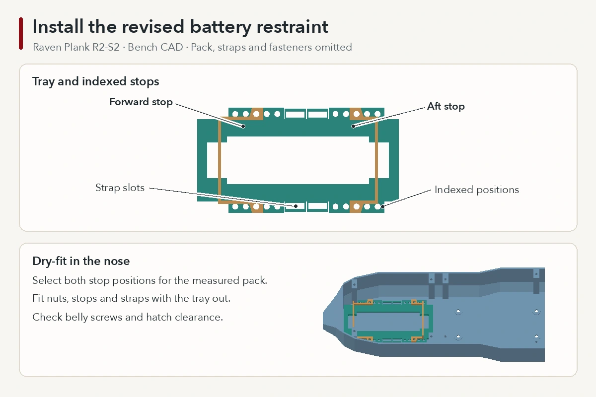
- Measure the actual pack and both lead exits. The CAD fit uses a 58 × 30 × 23 mm pack and five matching forward and aft stop positions spaced 4 mm apart. Choose the pair that seats the pack flat, limits fore-aft travel and leaves room for the leads.
- With the tray out, load four M2.5 thin square nuts from the center opening into the floor pockets. Feed both battery straps through the tray. The CAD check uses two 6 mm wide × 1 mm thick straps. Fit both end stops using four candidate M2 × 6 mm machine screws and four low-profile M2 hex nuts.
- Lower the tray into the nose with the hatch off. Fit four fully threaded M2.5 × 6 mm 90° countersunk machine screws from below. The modeled nut envelope is 5 × 5 × 1.6 mm. Check flush heads, engagement and suitable removable metal-thread retention. Keep the pocket roof intact and confirm no screw can touch the pack.
- Secure an inert pack surrogate with both straps for shake, inversion and pull checks. Then check the actual unplugged pack. Keep metal and sharp edges off its contact surfaces. The hatch should close without loading the strap buckle, touching the pack or pinching either lead. The straps and stops retain the pack.
Before you continue
The inert surrogate stays secure and the actual unplugged pack clears hardware, the hatch and both leads.
Fit the keyed servo mounts and route the leads
- Why this matters
- The strap retains the servo in its frame. Three screws secure the frame to each wing.
- Where to look
- The three keyed pockets are reached from the open underside well of each inner panel.
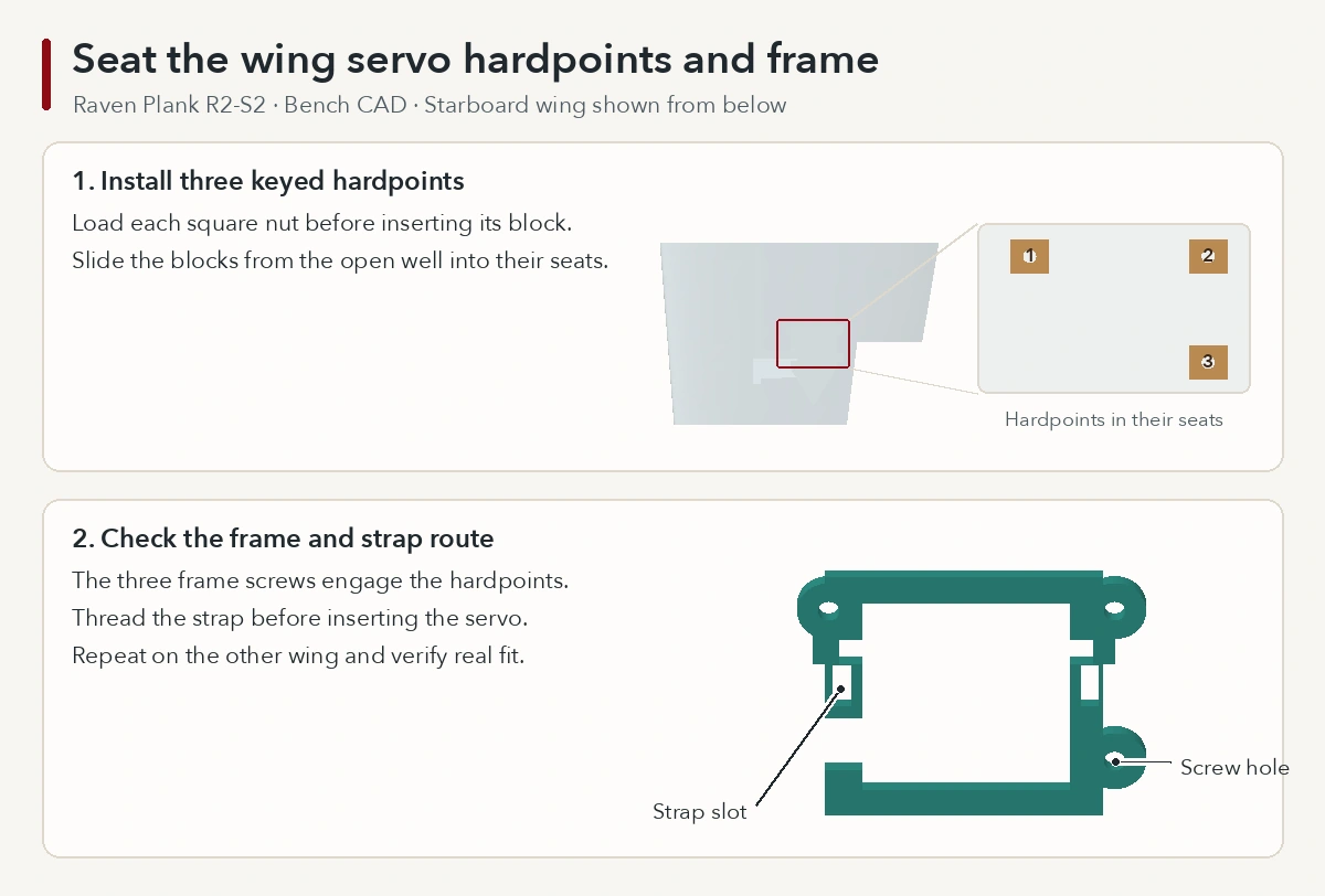
- Load the six PETG hardpoints with 5 × 5 × 2 mm M2.5 square nuts. From each open servo well, slide three blocks into the matching keyed pockets in the bare R2-S2 inner wing panel. Confirm each block seats fully.
- Before installing the servo, thread its flexible strap through the frame and over the empty cavity. The first bench fit allows up to 5.2 mm width and about 1 mm thickness. Insert the HS-65MG on its side and close the strap under the case. Check the tabs, lead exit and strap clearance with the real servo.
- Clamp each frame with three candidate M2.5 × 8 mm pan-head screws. Confirm engagement and free clearance for the case and linkage. Check servo-to-frame strap retention and frame-to-wing screw retention separately.
- Route the extension leads through their wing channels before closing or bonding the wing seams. Label left CH1 and right CH2. With the propeller off, verify that both frames remain seated through the intended servo and linkage movement.
Before you continue
All six hardpoints seat, both frames stay flush, and the straps, leads and horns clear through the intended travel.
Dry-fit both spars, wing panels and linkages
- Why this matters
- The continuous tubes align the wing panels and bridge the panel joints.
- Where to look
- Fit both bare tubes across the pod first, then seat both inner and outer panels on the jig.
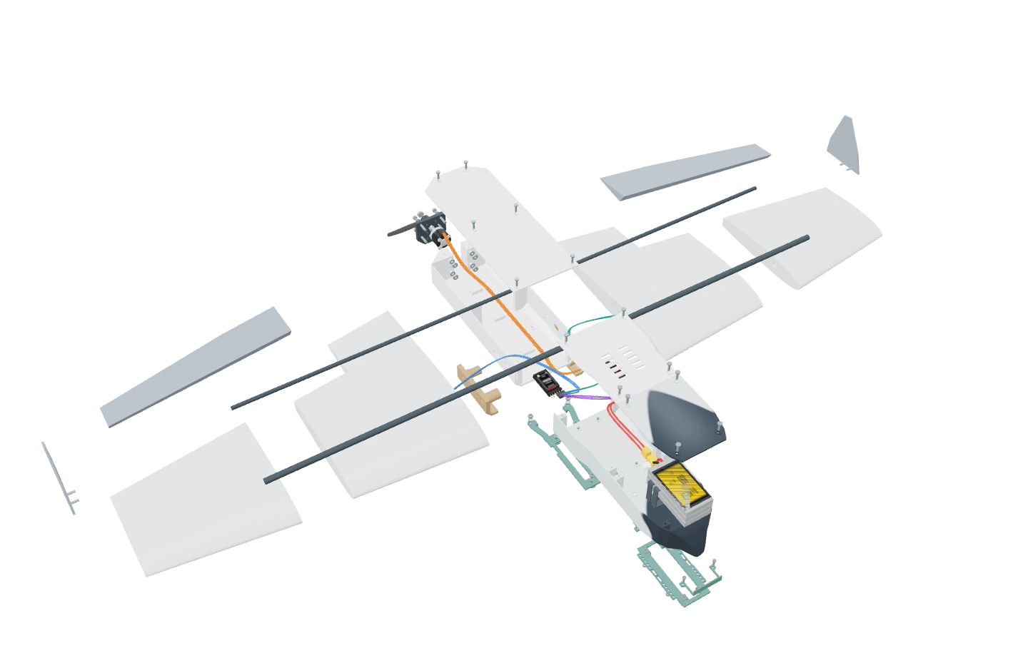
- Slide the continuous 6 mm × 640 mm main tube and 4 mm × 630 mm rear tube through the carriers and four panels. Check the 218 mm root seats, both inner-to-outer seams, the intentional wire entries and matching wing angles on a straight jig.
- Dry-fit both tip-fin locating pins and both elevons. Verify the bevel and fin clearance. Select the two horn and pushrod sets after measuring the installed linkages. Keep positive mechanical retention at each linkage end.
- Check bonding compatibility and prepare an exact-build joint test before bonding. Dry-fit and test the wing-to-pod, panel-to-spar, tip-fin and hinge interfaces separately. Keep bonding material clear of the control gaps and wiring passages.
Before you continue
The panels seat without bending or binding the tubes, and the wire openings and elevon gaps stay clear.
Dry-fit the electronics and check the harness
- Why this matters
- Confirm real equipment placement and safe wire clearances with the splice and restraints installed.
- Where to look
- Inspect the keyed tray, wing lead entries and aft firewall before fitting the covers.
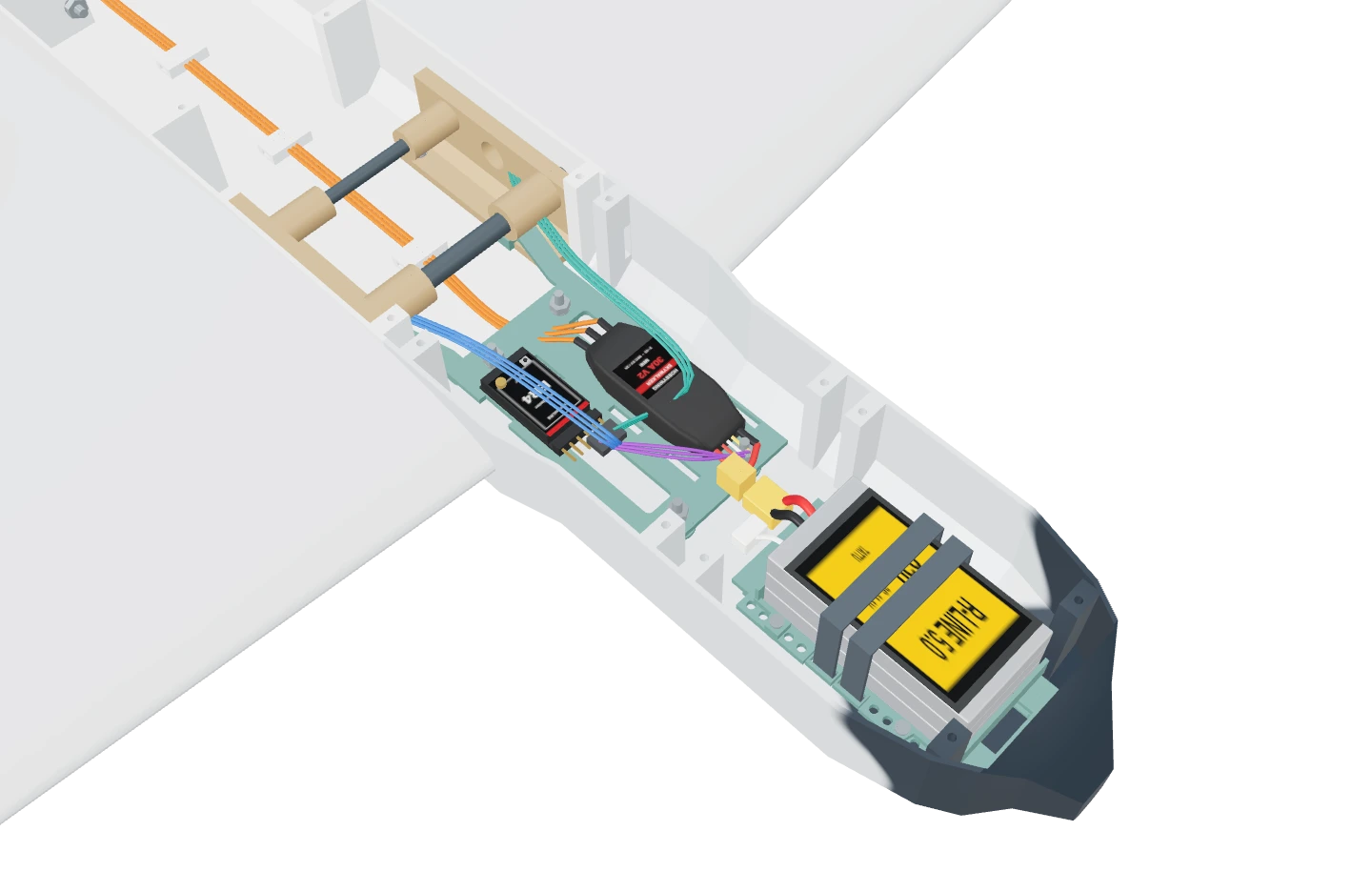
- Trial-fit the actual ESC and receiver on the keyed tray. The S1 digital check used the ESC 5 mm aft and receiver 10 mm forward of the original nominal positions. Select the actual positions after checking flat support, restraint, ventilation, antenna routing and lid clearance.
- With the firewall loose, check the motor screws against the actual thread depth and rotor clearance. Check the four firewall bolts with washers and locknuts. Route the phase leads through the firewall, then verify clearance past the splice, spars and moving parts before adding strain relief.
- With the propeller off and battery unplugged, check the harness for continuity, shorts and XT30 polarity. The R2 reference radio plan uses ER4 CH1 for the left elevon, CH2 for the right elevon and CH3 for ESC throttle and BEC. Check the actual receiver markings for signal, power and ground. Use 50 Hz for the HS-65MG outputs.
- Secure and insulate loose connectors and unused leads. With the battery disconnected, close each hatch without trapping wires. Keep the motor and antenna wiring clear of moving parts and the carbon tubes. Verify the wire paths on the assembled build.
Before you continue
The harness checks pass with the pack disconnected and the hatches close freely over the secured equipment.
Record balance, retention and propeller-off control checks
- Why this matters
- Record the fit and control results for the exact airframe and identify the work still needed before flight.
- Where to look
- Observe the elevons from behind with the propeller removed during the radio checks.
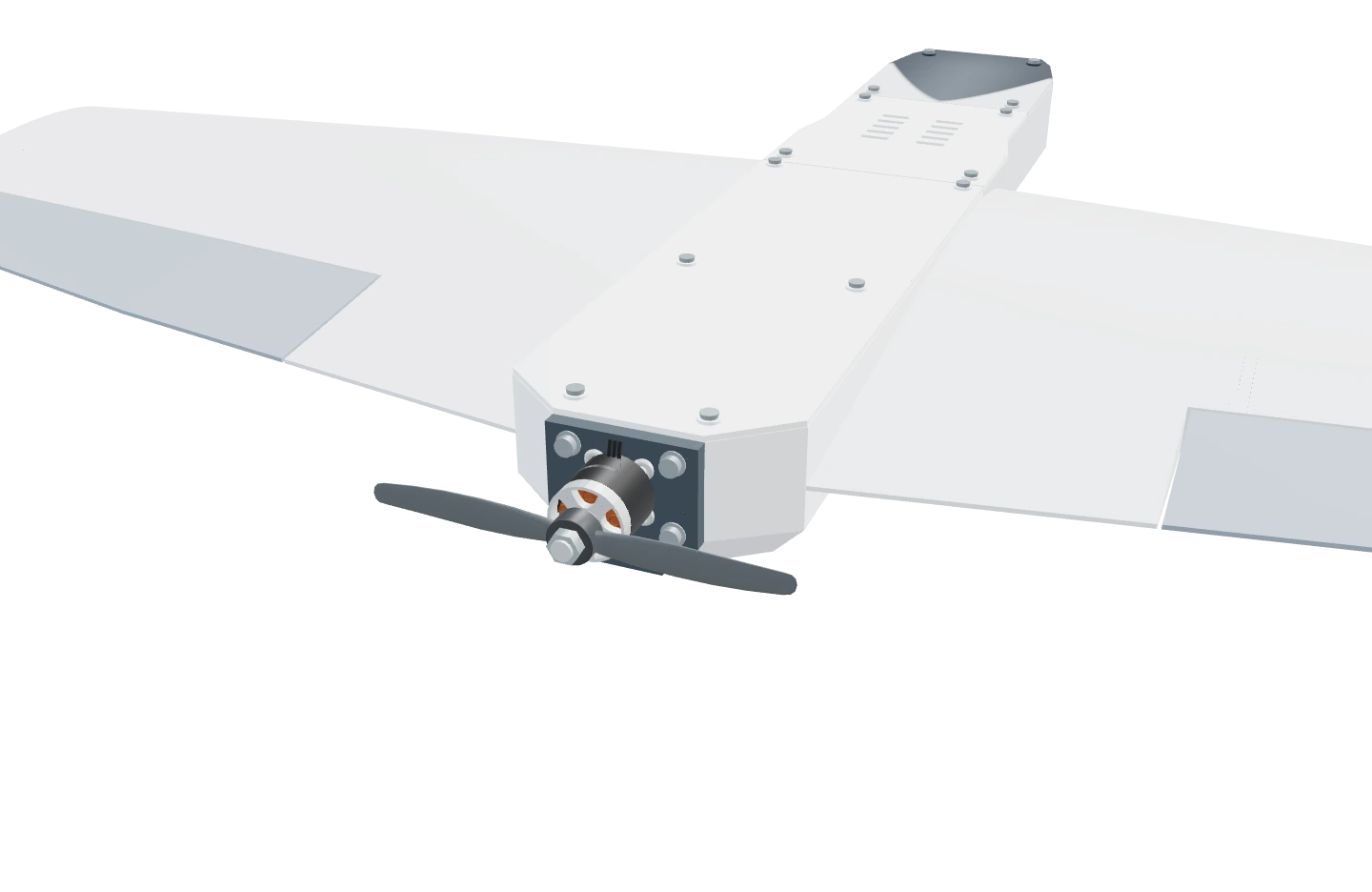
- Weigh the complete airframe with the intended unplugged pack installed. Record pack position, fore-aft and lateral balance, materials, measured screw grip, and any interference or seam movement. A flight CG, trim and control throws remain open for this revision.
- Keep the propeller off for radio checks. Verify throttle cut, motor-off failsafe and link recovery. Viewed from behind, pitch up raises both elevon trailing edges. Roll right raises the right trailing edge and lowers the left. Check the intended motion for binding, loosening, supply voltage sag or resets.
- With the pack unplugged, verify propeller fit and its full swept clearance by hand. Use a guarded independent fixture for any powered propulsion test, and compare current, vibration and temperature with the actual components’ limits.
- Keep this assembly on the bench until the exact build has passed physical joint and retention tests, balance and control review, and the appropriate propulsion checks. A fit check alone gives no measured load capacity.
Before you continue
Record measured results for this build and keep the release status at bench fit until the remaining checks are complete.
Checks to record
- Print fit, retention and repeatability for the exact materials, saved profiles and hardware.
- Load testing of the pod splice and floor mounts, wing joints, battery restraints, servo hardpoints and linkages.
- Installed mass and balance, allowable CG, trim, control throws, failsafe and guarded propulsion results.
- Controlled flight evidence for this exact revision.