
3D printed RC aircraft · Revision 0.2.1
Raven-Scout RC
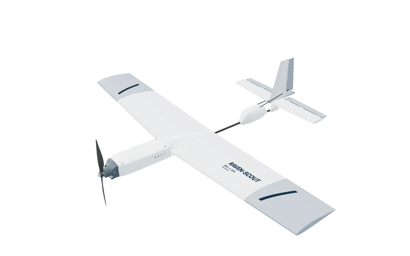
A three-channel electric trainer with a streamlined power pod, fitted wing roots and enclosed tail servos.
- Wingspan
- 1,000 mm before tip caps
- Wing section
- NACA 2412
- Configuration
- Three-channel electric trainer
Illustrated guide, bill of materials, STLs and Bambu Studio projects in one ZIP.
Kit edition 2 includes the corrected wing-root print orientations in its individual 3MFs and saved P1S project.
Loading the 3D view…
Exploded view inventory0.2.1
- Airframe
- Printed shells, fitted wing-root fairings, the revised tail servo cassette and carbon structure.
- Fasteners and linkages
- Pod, tray and tail fasteners, including M3 hatch locknuts and countersunk tray screws, plus hinge pins and control linkages.
- Electronics and wiring
- Battery, motor and propeller, ESC, receiver, tail servos, connectors and schematic wire routes.
- Items to check in the build guide
- Confirm the propeller retainer, motor screws, hinge-pin keepers, horn backing, clevises, straps and electronics restraints against the selected hardware.
A conventional trainer with a serviceable pod and tail
- Airframe
- The Scout’s printed wing sections meet the pod at shaped fairings, and a carbon boom carries the tail. The separate nose and tail hatches give access to the equipment at either end.
- How it’s controlled
- A propeller at the nose pulls the aircraft. Separate rudder and elevator servos under the tail hatch control yaw and pitch. Compare that layout with the Plank’s rear propeller and paired wing controls.
- Who it’s for
- A bench project for builders and supervised maker groups studying how a printed wing, carbon boom and accessible electronics fit together.
- Flight targets
- No range, speed or altitude targets are published for this revision.
This revision changes how the lower wing-root fairing and tail servo cassette clear the carbon boom.
Print files
The member build kit contains the STLs and print profiles for revision 0.2.1.
Print setup
- The changed enclosure parts use Bambu Lab P1S, 0.4 mm nozzle, 0.20 mm layers and Textured PEI for their fit-plate setup.
- PLA Basic enclosure trial uses 220 °C nozzle, 55 °C bed, two walls and a 5 mm brim. The colorFabb LW-PLA trial uses 240 °C nozzle, 60 °C bed, 0.50 flow, one wall, Arachne and an 8 mm brim.
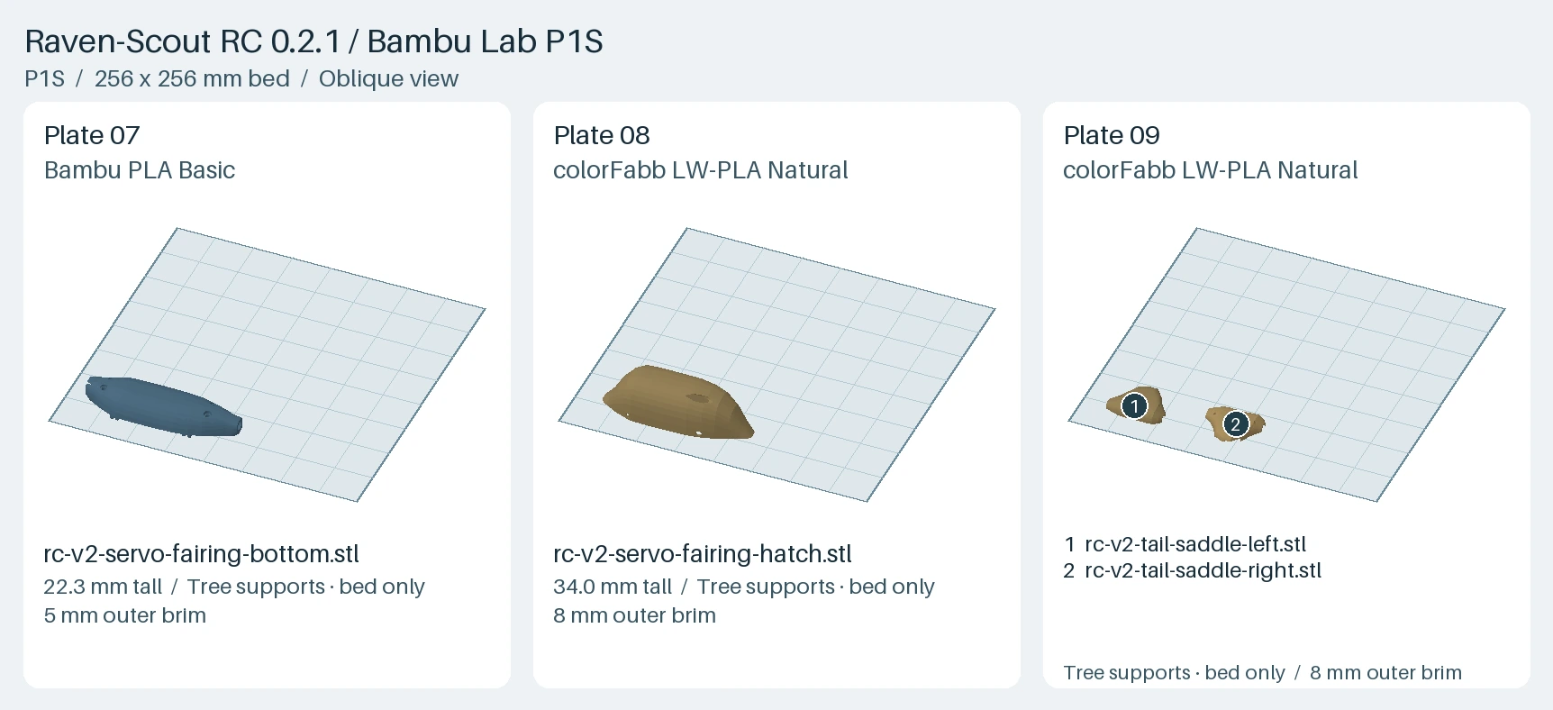
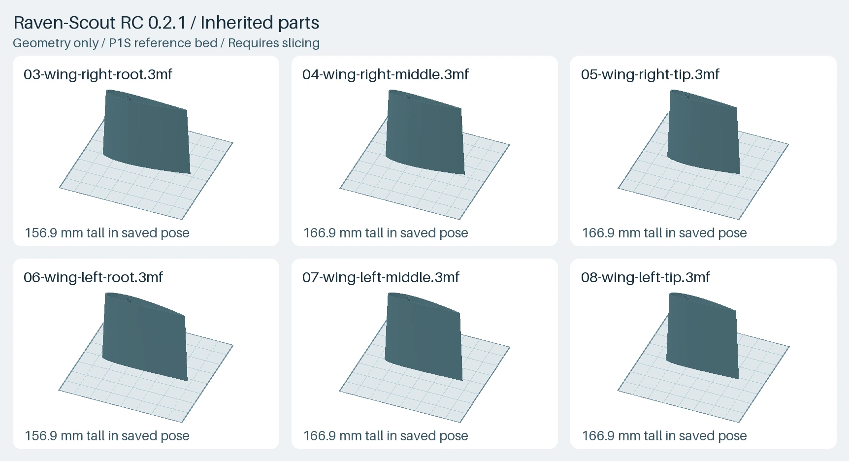
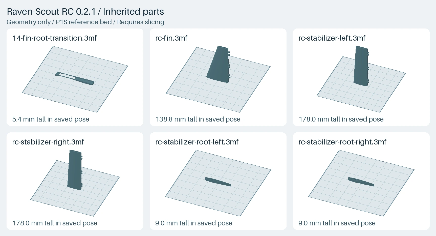
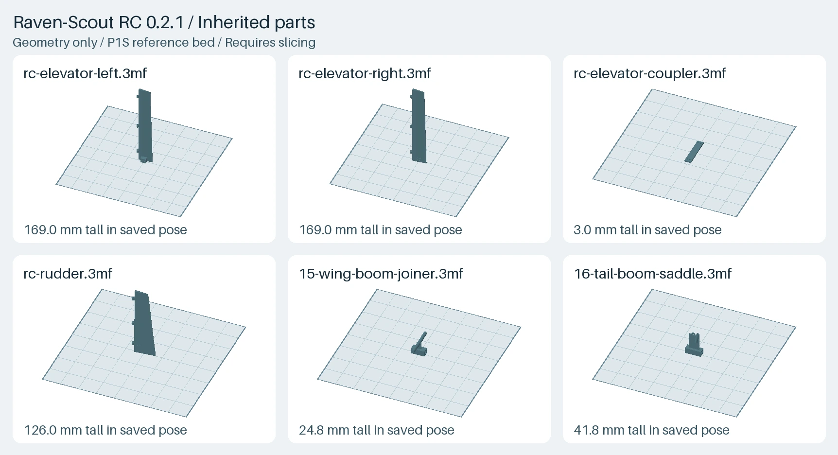
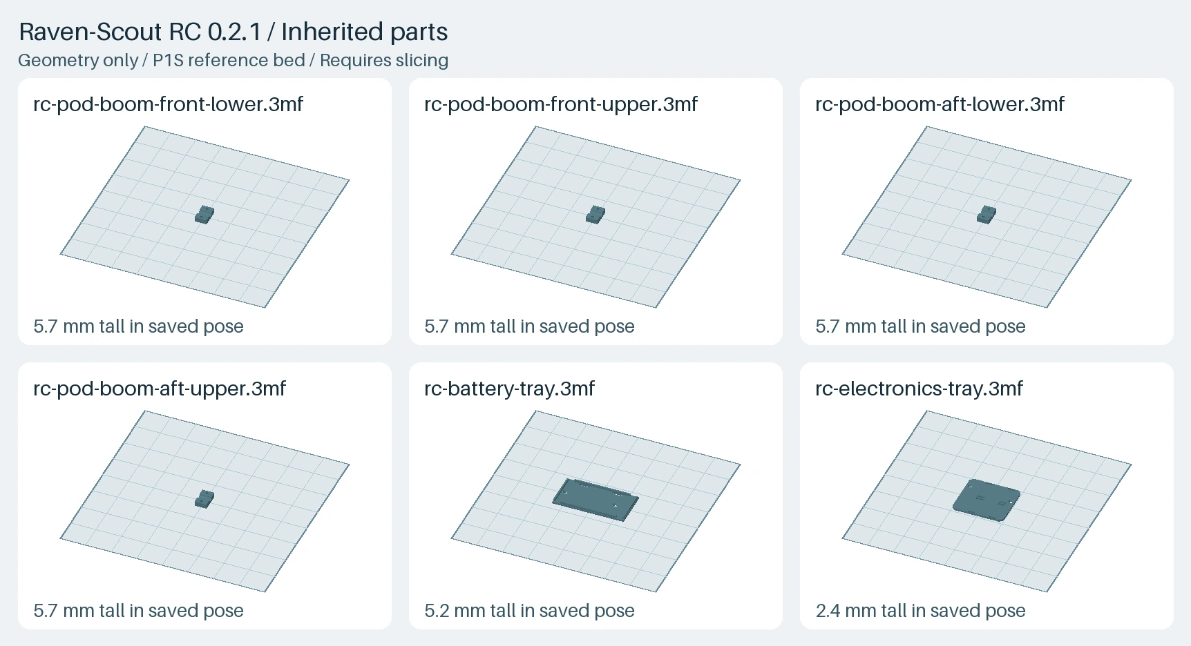
- The nine enclosure P1S projects cover 18 parts. Individual 3MF placements cover the 26 inherited parts.
- Kit edition 2 includes a separate P1S project for both wing-root transitions and both stabilizer roots. Individual 3MFs are also included.
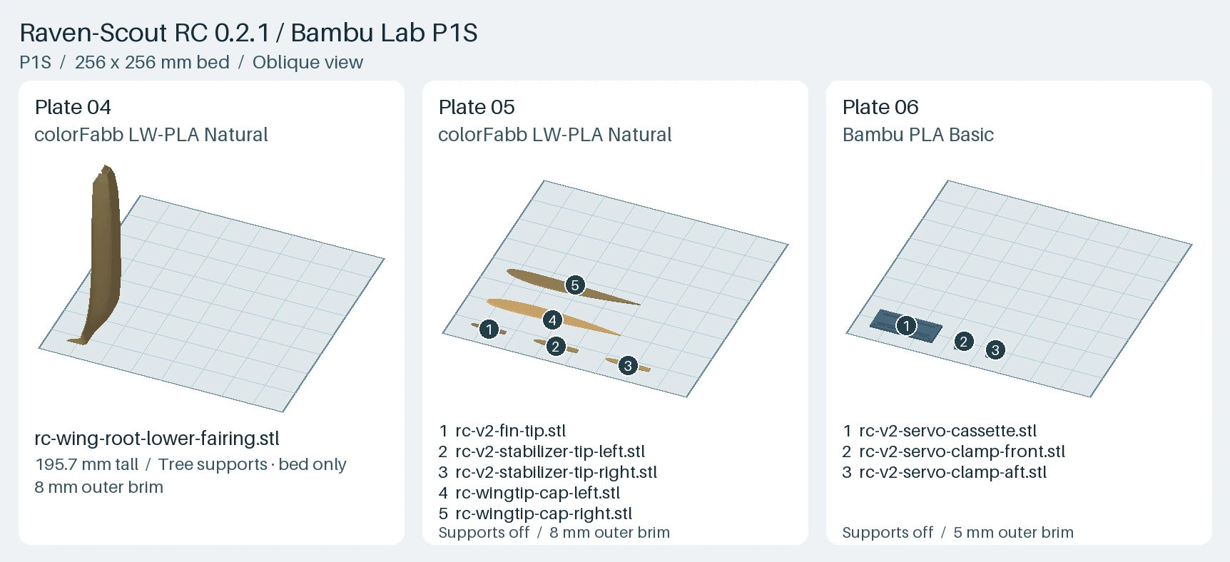
- Use the 0.2.1 project on plate 04 for the lower wing-root fairing and on plate 06 for the servo cassette.
- Kit edition 2 places both wing-root transitions with the uncut outboard face on the bed. Keep the saved orientation. See the wing-root transition slice settings and orientation
View the 44 printed parts
Images show the exported meshes for this revision. Each part is shown at its own scale.
| Part and STL filename | Image | Quantity | Material |
|---|---|---|---|
Wing root transition rightrc-wing-root-transition-right.stl | 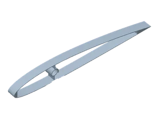 | 1 | LW-PLA |
Wing root transition leftrc-wing-root-transition-left.stl | 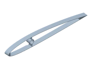 | 1 | LW-PLA |
Wing right root03-wing-right-root.stl | 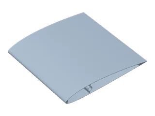 | 1 | LW-PLA |
Wing right middle04-wing-right-middle.stl | 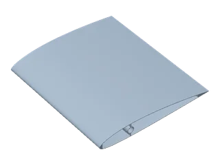 | 1 | LW-PLA |
Wing right tip05-wing-right-tip.stl | 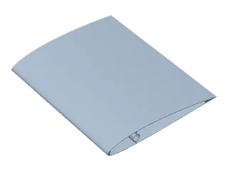 | 1 | LW-PLA |
Wing left root06-wing-left-root.stl | 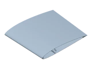 | 1 | LW-PLA |
Wing left middle07-wing-left-middle.stl | 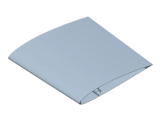 | 1 | LW-PLA |
Wing left tip08-wing-left-tip.stl | 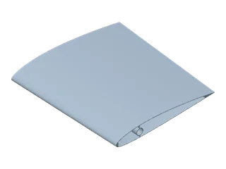 | 1 | LW-PLA |
Fin root transition14-fin-root-transition.stl | 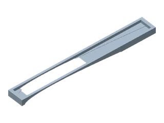 | 1 | PLA |
Wing boom joiner15-wing-boom-joiner.stl | 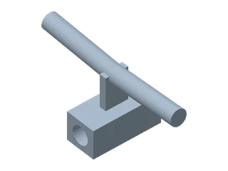 | 1 | PLA |
Tail boom saddle16-tail-boom-saddle.stl | 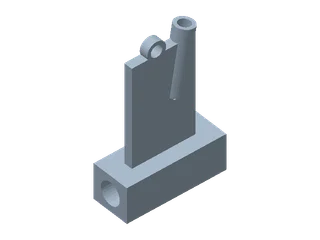 | 1 | PLA |
Stabilizer root rightrc-stabilizer-root-right.stl | 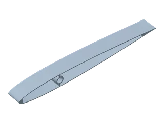 | 1 | LW-PLA |
Stabilizer root leftrc-stabilizer-root-left.stl | 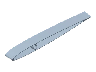 | 1 | LW-PLA |
Stabilizer rightrc-stabilizer-right.stl | 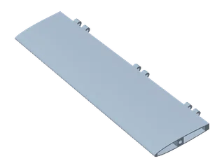 | 1 | LW-PLA |
Stabilizer leftrc-stabilizer-left.stl | 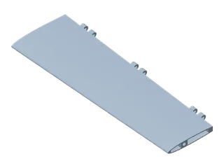 | 1 | LW-PLA |
Elevator rightrc-elevator-right.stl | 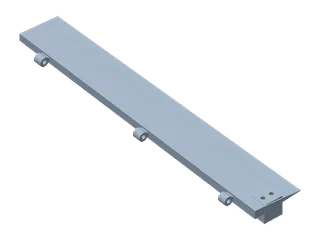 | 1 | LW-PLA |
Elevator leftrc-elevator-left.stl | 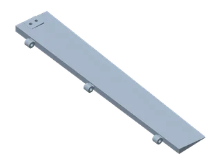 | 1 | LW-PLA |
Elevator couplerrc-elevator-coupler.stl | 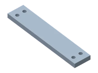 | 1 | PLA |
Finrc-fin.stl | 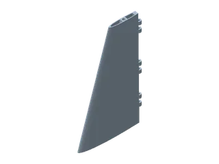 | 1 | LW-PLA |
Rudderrc-rudder.stl | 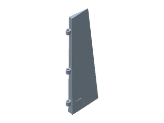 | 1 | LW-PLA |
Power podrc-power-pod.stl | 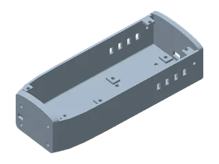 | 1 | PLA |
Motor firewall transferrc-motor-firewall-transfer.stl | 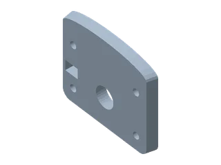 | 1 | PLA |
Power pod hatchrc-power-pod-hatch.stl | 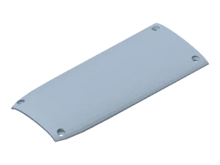 | 1 | PLA |
Motor cowlrc-motor-cowl.stl | 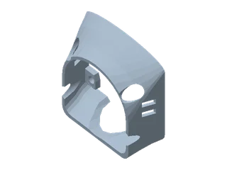 | 1 | PLA |
Battery trayrc-battery-tray.stl | 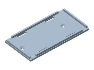 | 1 | PLA |
Electronics trayrc-electronics-tray.stl | 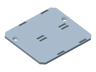 | 1 | PLA |
Pod boom front upperrc-pod-boom-front-upper.stl | 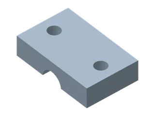 | 1 | PLA |
Pod boom front lowerrc-pod-boom-front-lower.stl | 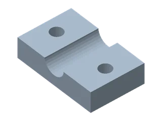 | 1 | PLA |
Pod boom aft upperrc-pod-boom-aft-upper.stl | 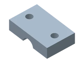 | 1 | PLA |
Pod boom aft lowerrc-pod-boom-aft-lower.stl | 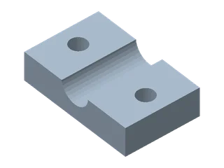 | 1 | PLA |
Wing root upper fairingrc-wing-root-upper-fairing.stl | 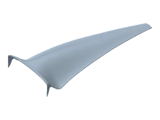 | 1 | LW-PLA |
Wing root lower fairingrc-wing-root-lower-fairing.stl | 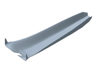 | 1 | LW-PLA |
Wingtip cap rightrc-wingtip-cap-right.stl | 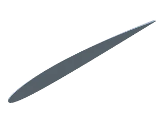 | 1 | LW-PLA |
Wingtip cap leftrc-wingtip-cap-left.stl | 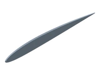 | 1 | LW-PLA |
Servo fairing bottomrc-v2-servo-fairing-bottom.stl | 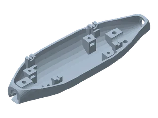 | 1 | PLA |
Servo fairing hatchrc-v2-servo-fairing-hatch.stl | 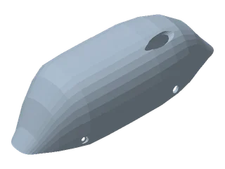 | 1 | LW-PLA |
Servo cassetterc-v2-servo-cassette.stl | 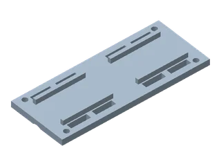 | 1 | PLA |
Servo clamp frontrc-v2-servo-clamp-front.stl | 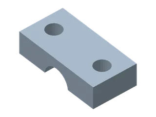 | 1 | PLA |
Servo clamp aftrc-v2-servo-clamp-aft.stl | 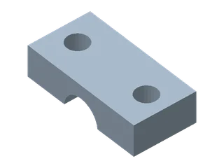 | 1 | PLA |
Tail saddle leftrc-v2-tail-saddle-left.stl | 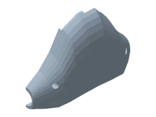 | 1 | LW-PLA |
Tail saddle rightrc-v2-tail-saddle-right.stl | 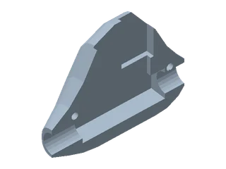 | 1 | LW-PLA |
Stabilizer tip leftrc-v2-stabilizer-tip-left.stl |  | 1 | LW-PLA |
Stabilizer tip rightrc-v2-stabilizer-tip-right.stl |  | 1 | LW-PLA |
Fin tiprc-v2-fin-tip.stl |  | 1 | LW-PLA |
Workshop tools
Use your existing workshop equipment where suitable. The reference printer and these tools are budgeted separately.
- Power, geometry and mass measurement equipment: Measure installation and loaded operation before any flight trial. Use a suitable inline DC power meter with matching XT60 connections, a multimeter, temperature probe, calipers, gram scale, balance fixture and control-travel gauge. Check the meter and lead ratings for the full test range. Choose rated meters and fixtures for the planned checks.
- Restrained test fixture and protective equipment: Keep the assembled aircraft restrained during reviewed propulsion checks. Use a stable fixture, suitable eye protection and clear separation from the propeller sweep. Use the adhesive maker's gloves and eye protection for bonding. Begin all radio checks with the propeller removed. Choose and qualify a stable restrained fixture and appropriate eye protection.
Bill of materials
Aircraft parts, assembly supplies, and radio and charging gear for revision 0.2.1.
Printed-part images show the exported meshes. Hardware and supply drawings help identify items. Images are not to scale.
Download BOM (CSV)Scroll each table sideways to see specifications and supplier links.
Printed parts and filament46 items
| Item | Image | Qty | Price (USD) and stock | Specification & sourcing |
|---|---|---|---|---|
| Wing root transition right | | 1 | Print from the kit | LW-PLA. 179.9 × 21.7 × 10.0 mm in the supplied print pose. STL filename rc-wing-root-transition-right.stl. Inherited part. Geometry export is supplied for a separate slice review. |
| Wing root transition left | | 1 | Print from the kit | LW-PLA. 179.9 × 21.7 × 10.0 mm in the supplied print pose. STL filename rc-wing-root-transition-left.stl. Inherited part. Geometry export is supplied for a separate slice review. |
| Wing right root | | 1 | Print from the kit | LW-PLA. 179.1 × 21.6 × 156.9 mm in the supplied print pose. STL filename 03-wing-right-root.stl. Inherited part. Geometry export is supplied for a separate slice review. |
| Wing right middle | | 1 | Print from the kit | LW-PLA. 166.6 × 20.0 × 166.9 mm in the supplied print pose. STL filename 04-wing-right-middle.stl. Inherited part. Geometry export is supplied for a separate slice review. |
| Wing right tip | | 1 | Print from the kit | LW-PLA. 153.3 × 18.5 × 166.9 mm in the supplied print pose. STL filename 05-wing-right-tip.stl. Inherited part. Geometry export is supplied for a separate slice review. |
| Wing left root | | 1 | Print from the kit | LW-PLA. 179.1 × 21.6 × 156.9 mm in the supplied print pose. STL filename 06-wing-left-root.stl. Inherited part. Geometry export is supplied for a separate slice review. |
| Wing left middle | | 1 | Print from the kit | LW-PLA. 166.6 × 20.0 × 166.9 mm in the supplied print pose. STL filename 07-wing-left-middle.stl. Inherited part. Geometry export is supplied for a separate slice review. |
| Wing left tip | | 1 | Print from the kit | LW-PLA. 153.3 × 18.5 × 166.9 mm in the supplied print pose. STL filename 08-wing-left-tip.stl. Inherited part. Geometry export is supplied for a separate slice review. |
| Stabilizer root right | | 1 | Print from the kit | LW-PLA. 89.8 × 8.1 × 9.0 mm in the supplied print pose. STL filename rc-stabilizer-root-right.stl. Inherited part. Geometry export is supplied for a separate slice review. |
| Stabilizer root left | | 1 | Print from the kit | LW-PLA. 89.8 × 8.1 × 9.0 mm in the supplied print pose. STL filename rc-stabilizer-root-left.stl. Inherited part. Geometry export is supplied for a separate slice review. |
| Stabilizer right | | 1 | Print from the kit | LW-PLA. 60.9 × 8.0 × 178.0 mm in the supplied print pose. STL filename rc-stabilizer-right.stl. Inherited part. Geometry export is supplied for a separate slice review. |
| Stabilizer left | | 1 | Print from the kit | LW-PLA. 60.9 × 8.0 × 178.0 mm in the supplied print pose. STL filename rc-stabilizer-left.stl. Inherited part. Geometry export is supplied for a separate slice review. |
| Elevator right | | 1 | Print from the kit | LW-PLA. 33.1 × 11.6 × 169.0 mm in the supplied print pose. STL filename rc-elevator-right.stl. Inherited part. Geometry export is supplied for a separate slice review. |
| Elevator left | | 1 | Print from the kit | LW-PLA. 33.1 × 11.6 × 169.0 mm in the supplied print pose. STL filename rc-elevator-left.stl. Inherited part. Geometry export is supplied for a separate slice review. |
| Fin | | 1 | Print from the kit | LW-PLA. 81.2 × 10.7 × 138.8 mm in the supplied print pose. STL filename rc-fin.stl. Inherited part. Geometry export is supplied for a separate slice review. |
| Rudder | | 1 | Print from the kit | LW-PLA. 42.3 × 6.7 × 126.0 mm in the supplied print pose. STL filename rc-rudder.stl. Inherited part. Geometry export is supplied for a separate slice review. |
| Wing root upper fairing | | 1 | Print from the kit | LW-PLA. 36.9 × 66.0 × 173.7 mm in the supplied print pose. STL filename rc-wing-root-upper-fairing.stl. Covered by the nine-plate P1S fit review. |
| Wing root lower fairing | | 1 | Print from the kit | LW-PLA. 39.5 × 66.0 × 195.7 mm in the supplied print pose. STL filename rc-wing-root-lower-fairing.stl. Use the updated lower fairing on P1S plate 04. Clear the supports from the boom notch before dry fitting. |
| Wingtip cap right | | 1 | Print from the kit | LW-PLA. 140.0 × 17.0 × 1.2 mm in the supplied print pose. STL filename rc-wingtip-cap-right.stl. Covered by the nine-plate P1S fit review. |
| Wingtip cap left | | 1 | Print from the kit | LW-PLA. 140.0 × 17.0 × 1.2 mm in the supplied print pose. STL filename rc-wingtip-cap-left.stl. Covered by the nine-plate P1S fit review. |
| Servo fairing hatch | | 1 | Print from the kit | LW-PLA. 123.7 × 42.0 × 34.0 mm in the supplied print pose. STL filename rc-v2-servo-fairing-hatch.stl. Covered by the nine-plate P1S fit review. |
| Tail saddle left | | 1 | Print from the kit | LW-PLA. 46.0 × 37.5 × 9.2 mm in the supplied print pose. STL filename rc-v2-tail-saddle-left.stl. Covered by the nine-plate P1S fit review. |
| Tail saddle right | | 1 | Print from the kit | LW-PLA. 46.0 × 37.5 × 9.2 mm in the supplied print pose. STL filename rc-v2-tail-saddle-right.stl. Covered by the nine-plate P1S fit review. |
| Stabilizer tip left | | 1 | Print from the kit | LW-PLA. 46.1 × 6.8 × 0.8 mm in the supplied print pose. STL filename rc-v2-stabilizer-tip-left.stl. Covered by the nine-plate P1S fit review. |
| Stabilizer tip right | | 1 | Print from the kit | LW-PLA. 46.1 × 6.8 × 0.8 mm in the supplied print pose. STL filename rc-v2-stabilizer-tip-right.stl. Covered by the nine-plate P1S fit review. |
| Fin tip | | 1 | Print from the kit | LW-PLA. 36.1 × 5.8 × 0.8 mm in the supplied print pose. STL filename rc-v2-fin-tip.stl. Covered by the nine-plate P1S fit review. |
| Fin root transition | | 1 | Print from the kit | PLA. 126.0 × 15.2 × 5.4 mm in the supplied print pose. STL filename 14-fin-root-transition.stl. Inherited part. Geometry export is supplied for a separate slice review. |
| Wing boom joiner | | 1 | Print from the kit | PLA. 24.0 × 54.2 × 24.8 mm in the supplied print pose. STL filename 15-wing-boom-joiner.stl. Inherited part. Geometry export is supplied for a separate slice review. |
| Tail boom saddle | | 1 | Print from the kit | PLA. 28.0 × 11.0 × 41.8 mm in the supplied print pose. STL filename 16-tail-boom-saddle.stl. Inherited part. Geometry export is supplied for a separate slice review. |
| Elevator coupler | | 1 | Print from the kit | PLA. 11.0 × 55.0 × 3.0 mm in the supplied print pose. STL filename rc-elevator-coupler.stl. Inherited part. Geometry export is supplied for a separate slice review. |
| Power pod | | 1 | Print from the kit | PLA. 166.0 × 66.0 × 43.2 mm in the supplied print pose. STL filename rc-power-pod.stl. Covered by the nine-plate P1S fit review. |
| Motor firewall transfer | | 1 | Print from the kit | PLA. 42.0 × 50.0 × 4.9 mm in the supplied print pose. STL filename rc-motor-firewall-transfer.stl. Covered by the nine-plate P1S fit review. |
| Power pod hatch | | 1 | Print from the kit | PLA. 154.8 × 65.8 × 8.3 mm in the supplied print pose. STL filename rc-power-pod-hatch.stl. Covered by the nine-plate P1S fit review. |
| Motor cowl | | 1 | Print from the kit | PLA. 45.5 × 48.0 × 15.8 mm in the supplied print pose. STL filename rc-motor-cowl.stl. Covered by the nine-plate P1S fit review. |
| Battery tray | | 1 | Print from the kit | PLA. 89.0 × 46.0 × 5.2 mm in the supplied print pose. STL filename rc-battery-tray.stl. Inherited part. Geometry export is supplied for a separate slice review. |
| Electronics tray | | 1 | Print from the kit | PLA. 64.0 × 59.0 × 2.4 mm in the supplied print pose. STL filename rc-electronics-tray.stl. Inherited part. Geometry export is supplied for a separate slice review. |
| Pod boom front upper | | 1 | Print from the kit | PLA. 15.0 × 24.0 × 5.8 mm in the supplied print pose. STL filename rc-pod-boom-front-upper.stl. Inherited part. Geometry export is supplied for a separate slice review. |
| Pod boom front lower | | 1 | Print from the kit | PLA. 15.0 × 24.0 × 5.8 mm in the supplied print pose. STL filename rc-pod-boom-front-lower.stl. Inherited part. Geometry export is supplied for a separate slice review. |
| Pod boom aft upper | | 1 | Print from the kit | PLA. 15.0 × 24.0 × 5.8 mm in the supplied print pose. STL filename rc-pod-boom-aft-upper.stl. Inherited part. Geometry export is supplied for a separate slice review. |
| Pod boom aft lower | | 1 | Print from the kit | PLA. 15.0 × 24.0 × 5.8 mm in the supplied print pose. STL filename rc-pod-boom-aft-lower.stl. Inherited part. Geometry export is supplied for a separate slice review. |
| Servo fairing bottom | | 1 | Print from the kit | PLA. 125.0 × 41.1 × 22.4 mm in the supplied print pose. STL filename rc-v2-servo-fairing-bottom.stl. Covered by the nine-plate P1S fit review. |
| Servo cassette | | 1 | Print from the kit | PLA. 65.0 × 26.5 × 4.8 mm in the supplied print pose. STL filename rc-v2-servo-cassette.stl. Use the updated cassette on P1S plate 06. Check that the underside relief clears the boom and the cassette seats fully. |
| Servo clamp front | | 1 | Print from the kit | PLA. 10.0 × 20.0 × 5.0 mm in the supplied print pose. STL filename rc-v2-servo-clamp-front.stl. Covered by the nine-plate P1S fit review. |
| Servo clamp aft | | 1 | Print from the kit | PLA. 10.0 × 20.0 × 5.0 mm in the supplied print pose. STL filename rc-v2-servo-clamp-aft.stl. Covered by the nine-plate P1S fit review. |
| colorFabb LW-PLA Natural, 1.75 mm | 1 spool | $7.88 225.14 g at $0.035/g $26.25 / 750 g spool Estimated use for all 26 LW-PLA parts, including sliced brims and supports. In stock Recheck stock · In stock at last check | Use for the parts listed as LW-PLA. Qualify foaming flow, seam adhesion, stiffness and the exact printer process on coupons. Part reference 030011. The link selects 1.75 mm Natural in the 750 g spool. Natural 1.75 mm, 750 g. The US storefront showed an in-stock sale price. | |
| Bambu PLA Basic Black, 1.75 mm | 1 spool | $3.25 180.91 g at $0.018/g $17.99 / 1000 g spool Estimated use for all 18 PLA parts, including sliced brims and supports. In stock Recheck stock · In stock at last check | Use for the parts listed as PLA. Review heat and structural suitability at the firewall, pod, clamps, coupler and hinges before operation. Part reference 10101 color code. The link selects Black (10101), 1 kg with spool. The selected 1 kg Black 10101 with-spool variant is marked in stock. |
Propulsion and onboard electronics8 items
| Item | Image | Qty | Price (USD) and stock | Specification & sourcing |
|---|---|---|---|---|
| Flite Test Radial 2212B 1050 kV v.2 | 1 motor | $24.99 / motor In stock Recheck stock · In stock at last check | Nose-mounted tractor motor. Flite Test specifies 3–4S, 3.5 mm bullets and a Ø27.5 × 26.5 mm case without the shaft. Measure the delivered mount face, bolt pattern and screw depth before drilling. Check the motor variant if buying Power Pack B Radial v.2. Obtain the exact motor current and temperature limits before testing with a propeller. Exact v.2 motor listing marks this product in stock. | |
| Flite Test 25 A ESC with XT60 and 3.5 mm bullets | 1 ESC | $24.99 / ESC In stock Recheck stock · In stock at last check | Drives the brushless motor and powers the receiver and both servos. Flite Test specifies 3–4S LiPo, BLHeli_S, 25 A continuous and a 5 V / 5 A BEC. Use the three-wire lead for regulated receiver power and insulate the unused red JST, which carries raw pack voltage. Confirm low-voltage behavior on the delivered ESC before relying on it. Power Pack B Radial v.2 lists the XT60/3.5 mm version. The exact XT60 and 3.5 mm bullet variant is marked in stock. | |
| HQ 9×4.5 Standard CCW propeller | 1 propeller | $5.00 / 2-pack In stock Recheck stock · In stock at last check | Tractor propeller with a 9 in diameter, 4.5 in nominal pitch and standard CCW rotation. With the battery disconnected, confirm the delivered hub bore, adapter seating, thread engagement and complete sweep clearance. The standalone listing contains two. Power Pack B lists two 9×4.5 propellers without an exact propeller SKU. Part reference FT4018510201. Two standard CCW props, UPC FT4018510201. Listing marks this pack in stock. | |
| Matched propeller adapter and retainer | 1 set | Source to choose | Seat and retain the commercial propeller. Match the supplied adapter, washer and positive retainer to the actual motor shaft and propeller hub. Motor listing states an M5 adapter thread. Confirm the actual parts, stack and retention before operating. Match the adapter, washer and retainer to the delivered motor and propeller hub. Check the adapter supplied with the motor and the delivered hub before buying separate hardware. Confirm the adapter and retention hardware supplied with the exact motor, then check the delivered propeller hub. | |
| Tattu 1300 mAh 3S 45C XT60 | 1 pack | $16.49 / battery In stock Recheck stock · In stock at last check | One standard 3S1P LiPo powers propulsion and the regulated radio rail. The pack is rated 11.1 V nominal and uses XT60 main and JST-XH family balance connectors. CAD uses the larger published 72 × 36 × 23 mm case envelope. Tattu's detailed table lists 35 mm nominal width. Measure and weigh the delivered pack and check strap and cable clearance. Part reference TAA13003S45X6. TAA13003S45X6 with XT60. US listing showed more than 100 units in stock. | |
| FlySky FS-iA6B receiver | 1 receiver | $13.90 / receiver In stock Recheck stock · In stock at last check | Deliver PWM to the ESC and both tail servos. AFHDS 2A, six PWM channels, 4.0–8.4 V supply, 47 × 26.2 × 15 mm case with dual 150 mm antenna leads. Allow lead exit and bind access and verify range in the final carbon/printed installation. Part reference FS-iA6B. The FS-iA6B receiver listing shows current stock. | |
| Flite Test 9G Analog Servo v.2 | 2 servos | $7.99 / servo 2 × $7.99 = $15.98 In stock · Required quantity unconfirmed Recheck stock · In stock at last check | Drive elevator and rudder independently. 4.8–6 V analog servos with 23.7 × 11.8 × 28 mm published dimensions. Verify ear spacing, output-axis position, arm and screw retention and unloaded and loaded movement. Power Pack B lists four 9 g servos. Install two of the exact v.2 model. Exact v.2 servo is marked in stock. The seller does not show whether two are available. | |
| Pololu 24 in / 600 mm twisted servo extension | 2 extensions | $7.30 / extension 2 × $7.30 = $14.60 In stock Recheck stock · In stock at last check | One 600 mm three-wire 22 AWG extension per servo. The displayed routes are about 437 mm to the elevator servo and 471 mm to the rudder servo, before service slack. Dry-fit each JR receiver end through the aft pod opening and check the delivered servo plug through the tail entry. Confirm connector fit, bend clearance, restraint, polarity and voltage at both servos under simultaneous load. Part reference 2168. The distributor link is for Pololu #2168. Item 2168. Pololu’s November 19 supply outlook showed 274 ready to ship. |
Airframe stock and linkages10 items
| Item | Image | Qty | Price (USD) and stock | Specification & sourcing |
|---|---|---|---|---|
| Servo arms, arm screws and body mounting hardware | 2 servo hardware sets | Source to choose | Attach each servo and retain its output arm. Confirm the arms and screws match the delivered servo spline. Resolve the case's actual mounting hardware and test retention and removal access together with the separately listed straps. Choose the arm and mounting hardware after checking the delivered spline, screws and case. Select hardware after checking the delivered servo spline and case. | |
| DU-BRO Mini-NY guided pushrod kit | 2 guided linkages | $3.59 / 2-linkage pack In stock Recheck stock · In stock at last check | Connect each servo to its tail control horn. 20 in long, 0.047 in diameter wire blanks with sleeves, threaded couplers and Mini Nylon Kwik-Links. Determine actual installed lengths and support locations. Confirm clevis/horn fit, retained closure and no buckling or binding. One #113 pack contains two wires, two sleeves and the four linkage ends. Part reference 113. The link selects #113, the two-linkage pack. DUB113 two-linkage pack is marked in stock. | |
| DU-BRO 1/2A nylon control horns | 2 horns | $1.39 / pack In stock Recheck stock · In stock at last check | Attach the elevator and rudder pushrods to the moving surfaces. One horn and nut plate per surface, using two included 2-56 × 3/8 in screws per horn. Transfer the measured hole pattern to the reinforced pad after checking the selected clevis and hinge alignment. Part reference 107. DUB107 pack of two is marked in stock. | |
| 2 mm smooth stainless hinge pin stock | 9 pin cuts | Price unconfirmed Stock unconfirmed | Pin three hinges on each elevator half and three on the rudder. Cut from nominal 2 mm 316/316L stainless rod. The CAD hinge stack is 14.5 mm and the provisional pin cut is 17.5 mm. Verify the keeper requirements on a measured print before cutting, then deburr and check free movement. One 1 ft rod provides stock for all nine cuts. Part reference 1335T22. Order McMaster part 1335T22. Confirm delivery on the product page. McMaster’s product page did not expose a current price or stock for part 1335T22 during this check. | |
| Positive hinge pin end retention | 9 keeper sets | Source to choose | Prevent axial migration of each pin. Select and qualify the exact end retention after checking the printed hinge stack and clearance. A friction fit by itself is insufficient. Verify positive retention and clearance on the measured hinge stack. Select each keeper after measuring the printed hinge stack and clearance. | |
| M2 elevator coupler hardware | 4 fastener sets | Source to choose | Join both elevator halves to the center coupler. Check an M2 × 18 mm cap screw against the 14.2 mm CAD grip stack and your printed parts. Use matching M2 × 0.4 nuts and washers, two sets per side. Verify the 3.8 mm head clears, and measure grip, retained thread engagement and free travel past the fin. Part reference SSC-M2-18-A2 (screw). Verify the actual grip, head clearance and nut engagement. Select and source the matching nuts and washers after checking the measured fit. The linked UK listing shows the nominal M2 × 18 mm screws in stock in GBP. Select matched nuts and washers after measuring the coupler. A complete USD kit is unconfirmed. | |
| Pultruded carbon wing spar tube | 2 × 490 mm cuts from one tube | $6.34 / 1 m tube In stock Recheck stock · In stock at last check | Measure, deburr and dry-fit at each corrected root transition. The 490 mm modeled lengths are derived from the retained 1 m geometry and its 10 mm root transitions. Part reference CF-TUBE-8MM-6MM-1000MM. Exact 8 × 6 × 1,000 mm tube. Seller showed 23 in stock. | |
| Pultruded carbon tail boom | 1 × 560 mm cut | $4.65 / 1 m tube In stock Recheck stock · In stock at last check | Measure OD and wall. Check clamp rotation, slip and local crushing without compromising the tube. Part reference CF-TUBE-6MM-4MM-1000MM. The exact 1,000 mm variant of the 6 × 4 mm tube showed 154 in stock. | |
| Pultruded carbon stabilizer rod | 1 × 380 mm cut from shared stock | $2.25 / 1 m rod One rod supplies both stabilizer and fin cuts. In stock Recheck stock · In stock at last check | Check alignment across the fixed stabilizer, root transitions and saddle. Part reference Carbon Fiber Rod 3mm x 1000mm. Exact 3 × 1,000 mm rod. Seller showed 20 in stock. One rod supplies both cuts. | |
| Pultruded carbon fin rod | 1 × 160 mm cut from shared stock | $2.25 / 1 m rod Shared with the stabilizer. Counted there. In stock Recheck stock · In stock at last check | Dry-fit the fin rod and verify it seats within the saddle and fixed fin. Part reference Carbon Fiber Rod 3mm x 1000mm. This cut uses the same 1 m rod stock as the stabilizer. Same 3 × 1,000 mm rod as the stabilizer. The shared purchase is counted once. |
Fasteners and assembly supplies14 items
| Item | Image | Qty | Price (USD) and stock | Specification & sourcing |
|---|---|---|---|---|
| Motor-to-firewall attachment hardware | 1 hardware set | Source to choose | Transfer motor loads through the fixed motor base to the firewall. Match fastener diameter, spacing, screw length and engagement to the actual motor and reviewed plate. Verify screw ends clear the windings and the mount retains the motor under vibration. Measure the actual motor bracket and firewall before choosing the screws. Choose screw length and engagement after measuring the delivered motor bracket and firewall. | |
| M3 motor cowl and firewall carrier hardware | 4 bolt, washer and locknut sets | Source to choose | Four through-bolts pass the cowl seats and transfer firewall. Use matching washers and locknuts. Measure the grip stack and verify tool access and retention with the propeller removed. Choose bolt length after measuring the cowl and firewall grip stack. Measure the printed stack before selecting bolts, washers and locknuts. | |
| M3 front and rear pod cradle hardware | 4 bolt, washer and locknut sets | $1.29 / 4 locknuts Prices locknuts only. Bolts and washers are excluded. In stock · Required quantity unconfirmed Recheck stock · In stock at last check | Close the two split cradles on the source boom. Two M3 × 0.5 through-bolts per cradle, flat washers and DU-BRO 2101 M3 locknuts. Select length from the measured stack. Check cradle contact and retention without drilling or crushing the carbon tube. Select any conforming shim after dry fit. Choose bolt length and any shim after dry-fitting the cradles to the delivered tube. The link is for the DU-BRO #2101 locknuts. Select bolts and washers after measuring the cradles. The DUB2101 four-locknut pack is in stock. Select bolts and washers after measuring the cradle. | |
| M3 flat-head battery tray fasteners | 2 fastener sets | Source to choose | Attach the battery tray with flush heads beneath the battery. Select M3 × 0.5 countersunk fasteners after measuring the actual seat and grip. Verify the head seats flush without abrading the battery and clears the retaining straps. Choose screw length after measuring the actual seat and grip. Measure the grip and verify the heads sit flush before selecting the screw length. | |
| M3 flat-head electronics tray fasteners | 2 fastener sets | Source to choose | Attach the removable electronics tray to the pod. Select two M3 × 0.5 countersunk fasteners after measuring the tray seats and stack. Verify the heads seat flush and the installed ends clear the ESC, receiver and wiring. Choose screw length after measuring the actual seat and grip. Measure the tray grip, seats and equipment clearance before selecting the screw length. | |
| M3 flat-head nose hatch hardware | 4 fastener sets | Source to choose | Four countersunk M3 through screws with matching locknuts. Confirm the delivered head fits the recessed crown and measure grip before selecting length. Choose screw length after checking the delivered head and recess. Check head fit and measure the recess and grip before selecting the screws. | |
| M3 tail enclosure boom clamp hardware | 4 fastener sets | Source to choose | Four M3 through-fastener sets retain the two separate clamp caps under the servo enclosure. Choose lengths from the measured stack and check clearance, compression and boom retention. Choose screw length after measuring the enclosure clamp stack. Measure the boom clamp stack to select the correct fasteners. | |
| 8 mm-class removable servo straps | 4 straps | Source to choose | Retain the two tandem servo cases in the removable cassette. Measure strap thickness and verify room for the arms and leads under the hatch. Check strap thickness, plug access and full arm travel with the cover fitted. Select straps after checking thickness, room at the servo arms and plug clearance. | |
| Padded battery strap and positive stop | 2 removable straps plus end pads | Source to choose | Restrain the battery at the reviewed position through handling and expected loads. Use straps up to 12 mm wide and select the length from the actual pack and tray. Qualify end pads, positive stop and strap anchors. Keep the pack accessible for disconnection. Size the straps and qualify the stop and pads on the delivered pack. Select the straps and pads after measuring the delivered battery and printed tray. | |
| ESC and receiver retainers, insulation and strain relief | 1 retention set | Source to choose | Hold electronics and route wiring clear of the propeller, joints and moving linkages. Retain the ESC and receiver separately with 8 mm-class removable ties and fitted insulating padding. Secure lead junctions, insulate the unused raw-voltage JST and preserve ESC airflow and receiver antenna clearance. Size the ties, pads and insulation on the delivered ESC, receiver and leads. Choose the retention and insulation after dry-fitting the actual equipment and leads. | |
| Bob Smith Industries Slow-Cure 30 Minute Epoxy | 1 resin and hardener set | $10.19 / 4½ oz set In stock Recheck stock · In stock at last check | Test the epoxy on representative joints before using it on the airframe. Use samples of the actual filament, carbon finish and firewall stock. Follow the maker's cure and protective equipment instructions. Keep epoxy away from hinges, fastener access and the motor. Part reference BSI-205. Exact BSI-205 4½ oz resin and hardener kit is listed in stock. | |
| Servo cassette and hatch screws | 8 × M2 × 8 mm screws and matching nuts | Source to choose | Four cassette and four hatch fasteners. Match the measured grip, pocket, tool access and positive retention. Confirm clearance to the linkage sweep. Part reference SSCF-M2-8-A4 (screw). Verify grip, retention and linkage clearance. Select the matching nuts after checking the pocket and grip. The linked UK seller lists M2 × 8 mm A4 screws in stock in GBP. Matching nuts and complete US sourcing remain unconfirmed. | |
| Tail saddle shell fasteners | 2 × M2 × 12 mm screws and matching nuts | Source to choose | Verify delivered screw heads, washers, accessible grip and positive retention. Keep both saddle covers clear of the boom, spar and moving tail. Part reference SSCF-M2-12-A4 (screw). Verify the head, washer stack and clearance. Select the matching nuts and washers after checking grip and access. The linked UK seller lists M2 × 12 mm A4 screws in stock in GBP. Matching nuts, washers and complete US sourcing remain unconfirmed. | |
| Removable seam tabs and fit shims | 1 bench supply set | Source to choose | Coupon-test low-profile removable tape on the actual LW-PLA. Use exterior seam tabs to dry-fit the wing fairings and tip caps. Qualify any pad or adhesive and all retained seams before operation. Coupon-test removable tape and verify the delivered shim thickness. Select tape and shim thickness after checking fit on printed samples. |
Radio and charging gear4 items
| Item | Image | Qty | Price (USD) and stock | Specification & sourcing |
|---|---|---|---|---|
| FlySky FS-i6X Mode 2 aircraft transmitter | 1 reusable transmitter | $59.90 / transmitter In stock Recheck stock · In stock at last check | Send independent throttle, elevator and rudder commands. AFHDS 2A airplane setup, Mode 2. Confirm receiver binding, throttle cut, channel assignment and the documented ground check. No tail mix or aileron outputs in this layout. Part reference FS-i6X. The link selects the Mode 2 transmitter by itself. The FS-iA6B receiver is listed separately. Mode 2 transmitter-only variant 43525242585255 is marked available. | |
| Energizer MAX AA alkaline transmitter cells | 4 1.5 V AA cells | $1.95 / 4-pack In stock Recheck stock · In stock at last check | Power the ground transmitter. Use a matched fresh set of four 1.5 V AA cells in the transmitter's holder. Verify polarity and transmitter voltage before testing. Part reference E91. Retail card of four E91-BP-4 AA cells. Exact pack is marked in stock. | |
| SkyRC B6ACneo AC/DC balance charger | 1 reusable charger set | $59.95 / charger In stock Recheck stock · In stock at last check | Balance-charge the disconnected 3S flight battery using the region-correct 100–240 V AC cord and both the main and balance connections. The charger package lists the AC cord as its only cable. Check direct XT60 and JST-XH balance reach. Obtain a compatible charge lead or balance adapter separately if needed. Follow both manuals for standard LiPo Balance CHG, polarity, cell count and charge limits. Part reference SK-100200. The linked SK-100200-02 is the US plug version. US plug SKU SK-100200-02. Seller showed 131 in stock. Check separately for any needed charge lead or adapter. | |
| Dynamite LiPo charge protection bag | 1 reusable bag | $12.99 / bag In stock Recheck stock · In stock at last check | Contain the disconnected pack during supervised charging. Use on a noncombustible surface and follow the battery maker's charging and storage instructions. Check lead exit and keep the charging setup attended. Part reference DYN1405. Dynamite lists DYN1405 as discontinued. Verify retailer availability before ordering. The manufacturer discontinued DYN1405. This retailer showed one in stock and excludes shipping to Alaska, California and Hawaii. |
Build guide
Build the NACA 2412 Scout with its rounded power pod, wing-root fairings and enclosed tail servos. The base wingspan is 1,000 mm before the tip caps.
Bambu Lab P1S, 0.4 mm nozzle, 0.20 mm layers, Textured PEI. PLA Basic uses a 220 °C nozzle, 55 °C bed, two walls and a 5 mm brim. colorFabb LW-PLA uses a 240 °C nozzle, 60 °C bed, 0.50 flow, Arachne, one wall and an 8 mm brim. Review the print inventory and bill of materials before starting. Use the 3D assembly reference to find parts on the aircraft. The plate images show how parts sit on the printer bed.
Explore the assembly, exploded view and components in 3D
Opening the RC assembly…
Assembly and component options
Move the elevator and rudder
Confirm travel limits on the fitted aircraft before any trial.
Overview
- Why this matters
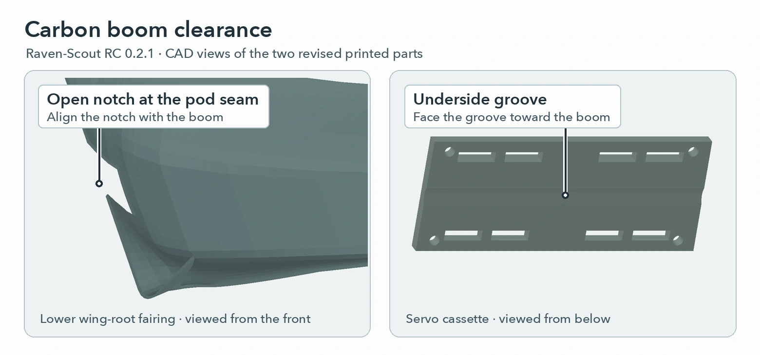
- Check the two interfaces around the carbon boom before committing to the rest of the prints. A part that catches on the boom can keep a fairing seam open or hold the servo tray above its mounts.
- Where to look
- The close-up shows the notch in the lower wing-root fairing and the groove under the servo cassette. Bring the fairing up from below the boom and lower the cassette from above onto its mounts.
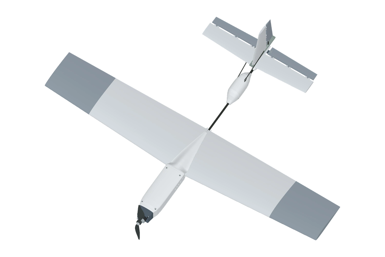
- Match the parts and hardware to the 0.2.1 inventory. Use the revised lower wing-root fairing and servo cassette for this revision.
- Print the lower wing-root fairing and servo cassette first. With the battery disconnected, dry-fit them on your nominal 6 mm boom. Check that the fairing seams close and the cassette seats fully on its mounts with the harness in place.
- Use Separated or hide Service covers in the 3D reference to locate the battery, receiver, ESC and tail servos.
- Remove the propeller and disconnect the battery for fitting and wiring.
Before you continue
Use the delivered nominal 6 mm boom with both parts cleaned. Measure and record the fairing seam and cassette seating at every mounting pad with the harness in place. Stop before bonding or powering the model if either part needs force or a screw would have to pull it into position.
Print the revised parts on the P1S
- Why this matters
- The saved plates show how each part is supported during printing. Check the parts that close around the boom first so you can correct a print issue before running the rest of the plates.
- Where to look
- Match the plate number and filename to the print inventory. Use the plate images for print orientation and the fitted model to see how the parts sit on the aircraft.
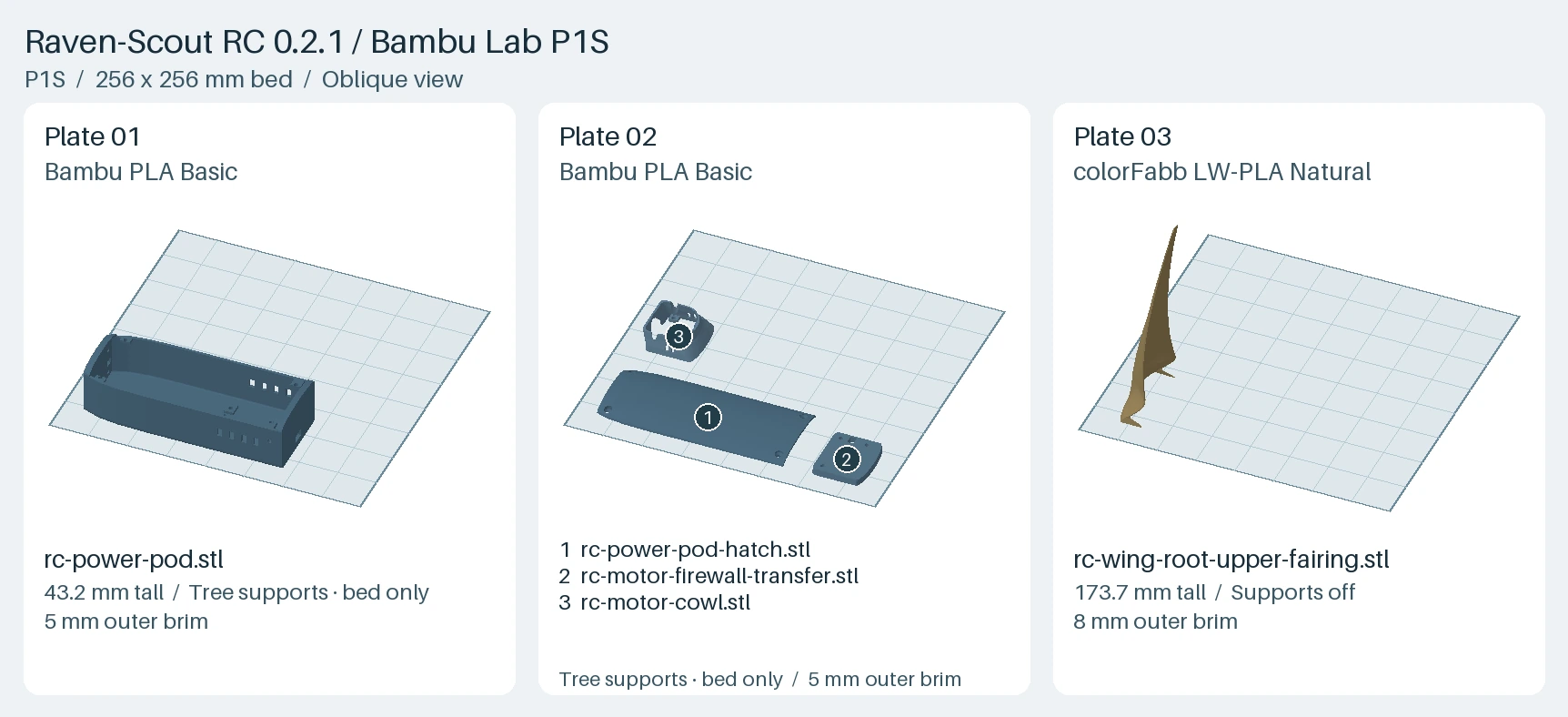
- Open the nine P1S projects for the 18 revised parts. Keep each plate’s saved material and layer settings.
- Preview supports, brims and first-layer contact. Check that the lower wing-root fairing’s tree supports can be removed through the split seam. Inspect the printed seams, bores and mating surfaces before assembly.
- Use the 0.2.1 plate 04 project for the lower wing-root fairing and plate 06 for the servo cassette. Clear support material from the fairing notch before fitting the boom.
Before you continue
Start with the 0.2.1 lower fairing on plate 04 and cassette on plate 06. Clear the fairing notch after printing and test both parts on the actual boom before printing the remaining plates.
Slice the inherited parts separately
- Why this matters
- The inherited parts have individual bed placements. Check the slice for each part so the first layers have enough contact and the channels stay open.
- Where to look
- In kit edition 2, each wing-root transition sits on the uncut face farther from the pod. The two stabilizer roots in the same project keep their original poses.
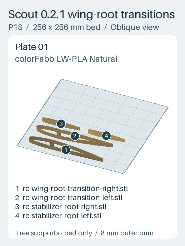
- Kit edition 2 places both wing-root transitions with the uncut outboard face on the bed. Keep the saved orientation.
- Use the saved wing-roots-outboard P1S project for both wing-root transitions and both stabilizer roots, or use the individual 3MFs. For a kit edition 1 copy, rotate only the two wing-root transitions 180° around X and place their uncut outboard faces on the bed.
- Keep the colorFabb LW-PLA profile and 8 mm outer brim. Use Tree (auto) supports with On build plate only. Leave auto-orient off when slicing.
- The reference slice generated no support paths. In Preview, check the first layer and verify that the nominal 8 mm spar bores stay clear of the brim. Remove the brim and dry-fit the carbon tubes before bonding.
- For other inherited parts, use the individual 3MF placements and set the material, supports and slicing settings for each part.
- Match wing and tail parts by side and section. Preview clearance and first-layer contact before printing.
Before you continue
Confirm the intended bed contact and inspect the spar openings in the slicer. After removing the brim, check the openings against the actual carbon tubes.
Wing, fairings and boom
- Why this matters
- The carbon spars locate the panels and the center joiner ties the two sides together. A trial assembly lets you check alignment while the panels and covers can still be removed.
- Where to look
- Choose Wing, fairings and boom in the 3D Highlight menu. Follow each row of separated panels from the center joiner out to its tip, then use Fitted to check where the fairing meets the nose pod.
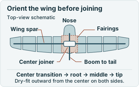
- Check the spar openings against the carbon tubes. Dry-fit each side in order from center transition to root, middle and tip.
- Seat the spar ends on the center joiner pins, then dry-fit the joiner on the bare boom. Keep the 0.2 mm center relief clear and check wing alignment and symmetry before bonding.
- Seat the fairings around the root with the harness in its channel. Fit the lower fairing from below and check that the notch clears the boom without loading the spars or pinching the harness.
- Dry-fit the matching tip caps. Use removable seam tabs for bench fitting. Test adhesive on the printed skin before bonding and keep it out of the wing passages.
Before you continue
Seat each panel and center joiner pin on the actual spars, keep the 0.2 mm center relief clear, and compare seam closure and incidence on both sides. Record the material, adhesive, cure and measured engagement for each bonded interface before reviewing its retention. Fit the fairing seam tabs with the harness routed, then remove and refit the fairings while checking that the wing seams, spars and connectors stay seated.
Nose and power pod
- Why this matters
- Test whether you can reach the battery and unplug it with the nose pod assembled. A component can fit on its own and still block a connector, a cooling path or a screw.
- Where to look
- In the nose close-up, the motor is ahead of the firewall. Follow the boom aft through both cradles, then locate the battery tray and the receiver and speed controller under the hatch.
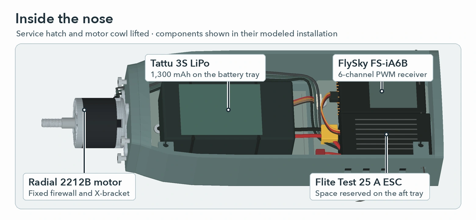
- Dry-fit the front and aft cradles around the boom. Leave the tube undrilled. Check screw, nut and tool access and verify that the cradles hold without crushing the tube.
- Fasten the firewall through its carrier holes. Transfer the actual motor bracket pattern before drilling, and check screw engagement and winding clearance.
- Place the battery and electronics in their trays. Fit the pack restraints and leave room for cooling, connector bends and disconnection. Seat the hatch and check that the screws sit flush and the leads stay clear.
- Dry-fit the cowl with the propeller removed. Check the motor bell, shaft, hub and adapter for clearance, and protect the leads from rubbing.
Before you continue
With the pack unplugged and propeller removed, check both boom cradles for axial slip, rotation and tube damage. Verify the firewall, cowl and tray fasteners seat with usable nut and tool access. Record the hardware and measured engagement. Confirm the battery stays restrained with the hatch open and the main plug can be reached without pulling its leads.
Enclosed tail controls
- Why this matters
- Fit the enclosure before the tail saddle closes off access along the boom. Setting up both linkages with the cover in place helps reveal interference you can miss with the cover off.
- Where to look
- Use the tail close-up to identify the forward elevator servo and the aft rudder servo. Trace each rod separately through its cover opening to the horn on the moving surface.
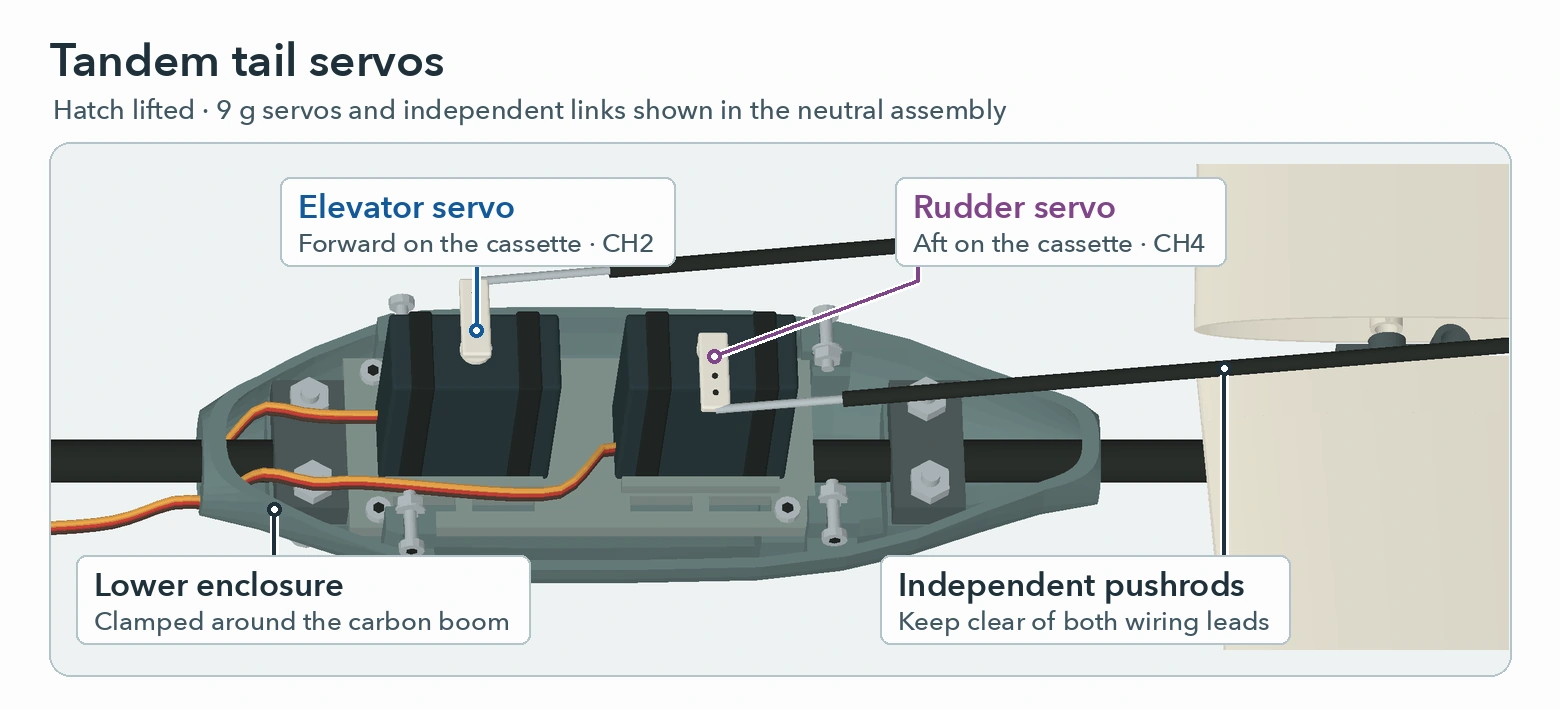
- Slide the lower servo enclosure onto the bare boom before installing the tail saddle. Fit both clamp caps. Check that the relief under the cassette clears the boom and the cassette sits fully on its mounting pads. Then center and secure both servos.
- Dry-fit both stabilizer roots, the outer stabilizers and the fin on their rods. Leave the 6 mm gap at the saddle. Measure where the rod ends sit flush before fitting the caps.
- Measure the hinge stacks and keeper space before cutting and deburring the 9 nominal 2 × 17.5 mm steel pins. Fit positive keepers at both ends. For the 4 coupler fasteners, check the grip and clearance of M2 × 18 mm screws on your print before fastening.
- Transfer the delivered horn patterns to their pads. Route the guided pushrods through the aft openings, fit the cover and connect the horns. Sweep each control and both together to check for binding.
- To remove the cover, disconnect the battery, remove the cover screws and disconnect both pushrods at the tail. Withdraw the rods from the cover openings. Check that the front tab clears as the cover lifts. Stop if the shell binds.
Before you continue
Measure all nine hinge stacks and confirm positive keepers at both ends of each pin. Check the four elevator coupler fasteners for seating, thread engagement and clearance from the fin through both controls' measured travel. With the battery disconnected, detach both tail pushrods and withdraw them from the cover openings. Remove the cover and cassette to check access to both boom clamp caps, then refit them and recheck neutral, free travel and guide retention.
Radio and wiring
- Why this matters
- Test the actual plug bodies before closing the covers. A wire may fit through an opening even when its insulated connector cannot pass.
- Where to look
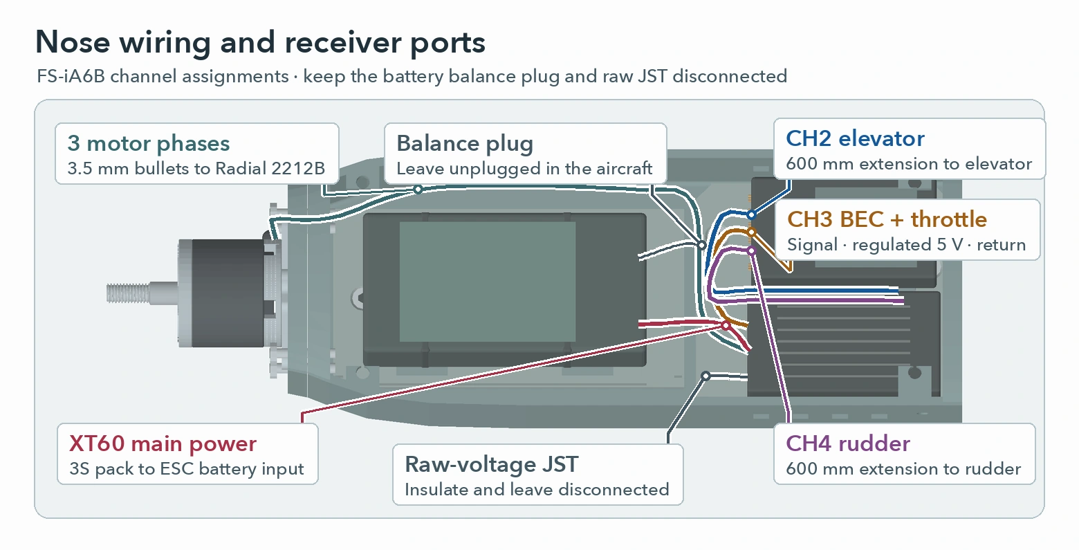
- Start with the full-airframe wiring drawing. The motor and battery connections stay in the nose. Follow the two tail servo routes through the wing root and along the boom, then use the nose close-up to identify their receiver channels.
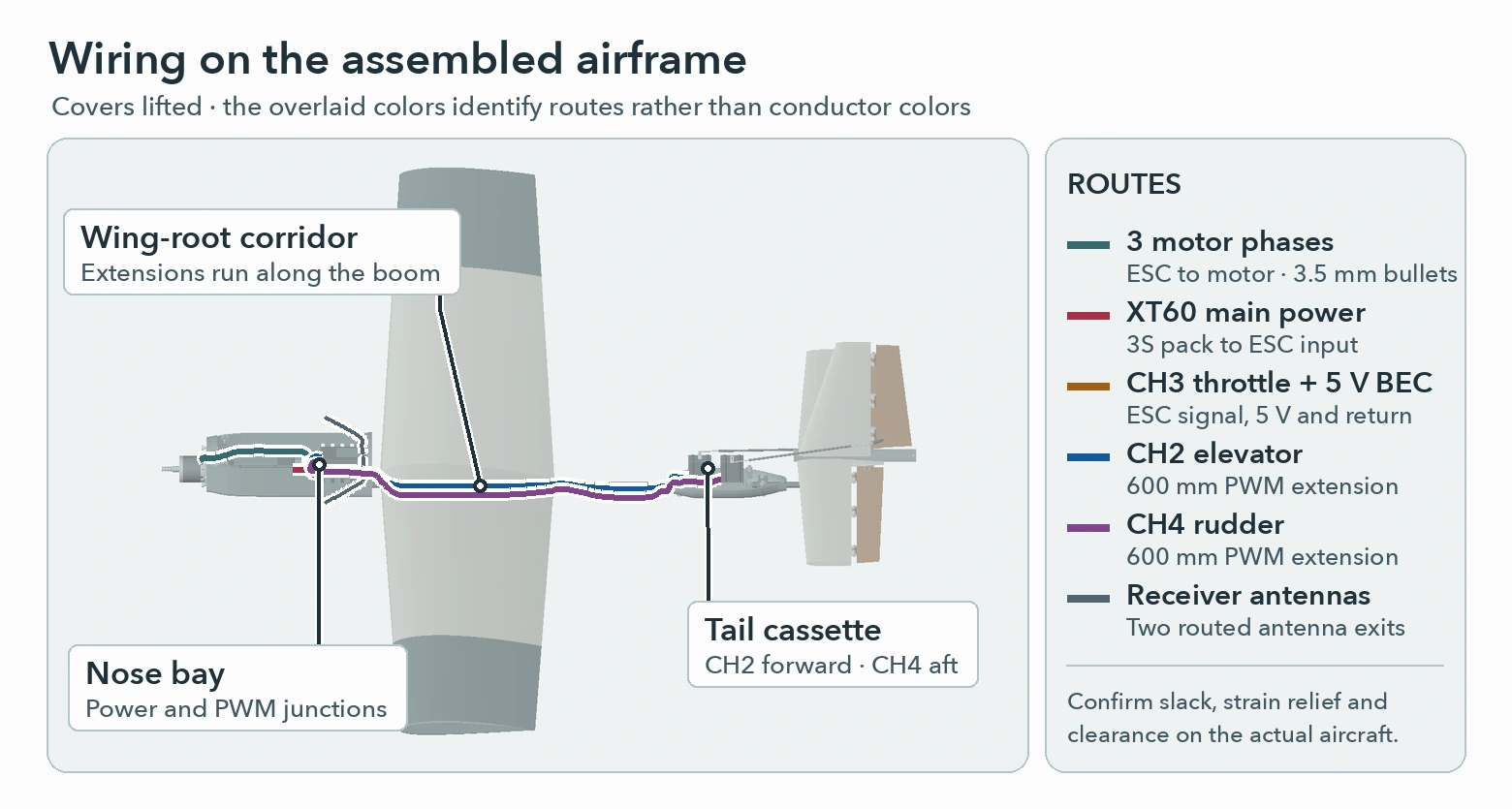
- With the battery disconnected, dry-fit the motor bullets through the 7 × 5 mm nose opening one at a time. Check the actual insulated connectors before fitting the cowl and firewall.
- Before closing the fairings, try feeding the smaller receiver ends of both servo extensions noseward through the 10 × 6 mm aft pod opening. Check the actual servo leads through the 10 × 4.3 mm tail entry. Keep the extension junctions accessible outside the tail shell and secure the leads along the boom clear of clamps and pushrods. Stop if the connectors or harness cannot pass without force.
- Match signal, positive and ground to the receiver markings. Leave the balance plug disconnected in the aircraft, insulate the red raw-battery JST and leave B/VCC free after binding.
- Support the connectors, leave service slack and route the antennas as FlySky specifies. Check the wiring channel and antenna exits with all covers fitted.
Before you continue
Trial-fit the actual insulated plugs through the pod and tail openings before closing the fairings. Keep both extension junctions accessible outside the tail shell and support them against separation. Open and refit each cover with power disconnected, then check connector seating, service slack, clamp clearance and both pushrods' full travel.
Connection map
- 3S Tattu flight battery → FT 25 A ESC battery input. Keyed XT60 main leads.
- FT 25 A ESC motor outputs → Radial 2212B motor. Three 3.5 mm bullets.
- ESC throttle and regulated BEC lead → FS-iA6B CH3. Three-wire PWM signal, regulated 5 V and return.
- Elevator servo → FS-iA6B CH2. Independent 600 mm straight-through three-wire PWM extension.
- Rudder servo → FS-iA6B CH4. Independent 600 mm straight-through three-wire PWM extension.
- FlySky FS-i6X → FlySky FS-iA6B. AFHDS 2A, fixed-wing Mode 2.
Ground checks
- Why this matters
- The measured mass and balance help a reviewer assess the exact build. Battery position affects how the aircraft balances, so record it along with the measurement.
- Where to look
- Weigh the assembled airframe with the intended battery secured and unplugged. Zero the scale with the empty cradle first if you use one. For balance, agree on a fixed reference and support method with the reviewer, then note where it balances along the nose-to-tail axis and whether either wing drops.
- With the propeller removed, bind the radio and program CH3 failsafe to the verified motor-off position. Check throttle cut and loss of signal separately. Verify motor rotation against the propeller markings. Confirm commanded up raises the elevator trailing edge and commanded right moves the rudder right as viewed from behind. Range-test the installed receiver and antennas with the covers fitted.
- Move both servos together with the covers fitted. Check linkage clearance and measure the receiver rail and both servo voltages under load against their device limits.
- Obtain documented current and temperature limits for the delivered motor before fitting the propeller for any powered test. With the battery disconnected, check propeller orientation, seating, retention and full sweep. Have an experienced reviewer assess a restrained power check and record voltage, current, temperatures, vibration and mount movement.
- Before flight, verify the ESC’s 3S low-voltage behavior or establish a separate pack-voltage monitoring method against the battery maker’s discharge limits. The receiver reports its regulated 5 V supply, so use the flight pack voltage for this check.
- Record all-up mass and balance with the flight battery installed. Establish a reviewed center-of-gravity range and control throws for this build before a flight trial.
Before you continue
Record the exact revision, printed materials and profiles, stock sizes, fasteners, adhesive and cure alongside measured mass, balance and pack position. Include seam and socket engagement, clamp movement, hinge-pin and coupler retention, and control travel after servicing. Have the exact joints and their bench load checks reviewed before a flight trial.