3D printed RC aircraft · Revision R1-A4
Raven Trainer R1-A4
A compact 440 mm electric trainer with a high wing, a carbon tail boom and two micro servos.
- Wingspan
- 440 mm
- Wing section
- NACA 2412-derived
- Configuration
- High-wing electric trainer
Illustrated guide, bill of materials, STLs and Bambu Studio projects in one ZIP.
Loading the 3D view…
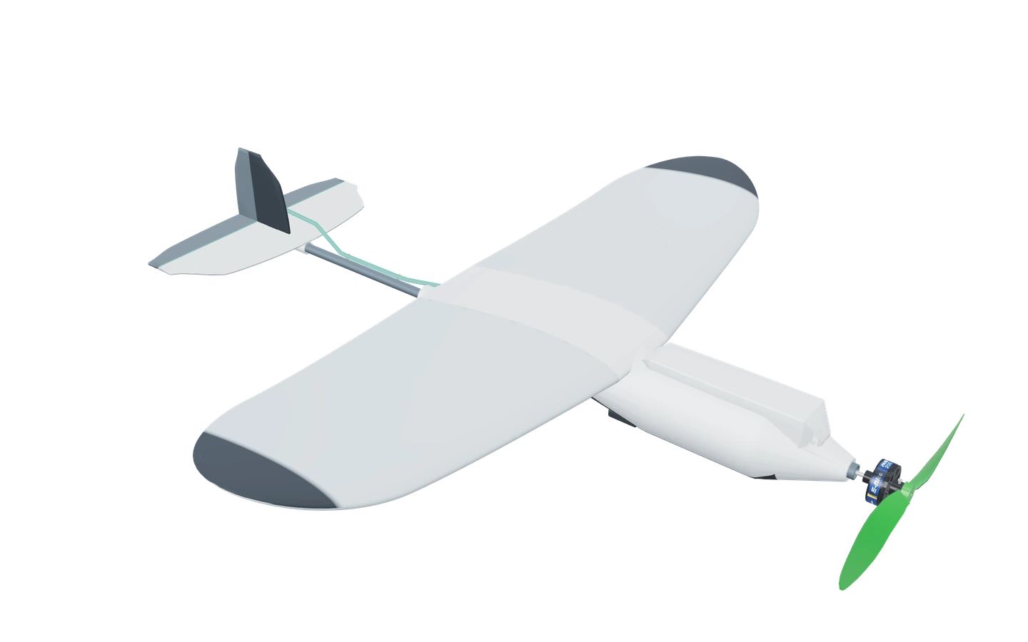
Exploded view inventoryR1-A4
- Airframe
- The D74 airframe with its printed wing and tail panels, carbon stock and removable hatch.
- Fasteners and linkages
- Five heat-set insert references, hatch and servo fasteners, control linkage positions and battery restraint references.
- Electronics and wiring
- Battery, motor and propeller, ESC, two servos, receiver, A3 Mini stabilizer and XT30 wiring.
- Items to check in the build guide
- Check the propeller adapter and keeper, horn attachments, battery pads and shims, and equipment restraints on the assembled model.
A compact trainer for studying balance and linkages
- Airframe
- The Raven Trainer uses 9 printed parts and a 222 mm carbon tail boom. R1-A4 moves the wing and tail together relative to the pod so builders can study how battery position affects balance.
- How it’s controlled
- The pod holds 2 HS-40 micro servos. Their pushrods run along the boom to the rudder and elevator, making the linkage path easy to trace at the bench.
- Who it’s for
- A project for supervised workshops and classrooms that want a compact airframe for demonstrating how mass placement, linkage movement and radio checks relate.
- Flight targets
- No range, speed or altitude targets are published for this revision.
Print files
The member build kit contains the STLs and print profiles for revision R1-A4.
Print setup
- The reference projects use a Bambu Lab P1S, 0.4 mm nozzle, textured PEI plate and 0.20 mm layers.
- Print the PLA Basic body diagonally on its belly. The pod project uses build-plate-only supports for the body and hatch. Clear the wiring, carbon and linkage passages before dry fitting.
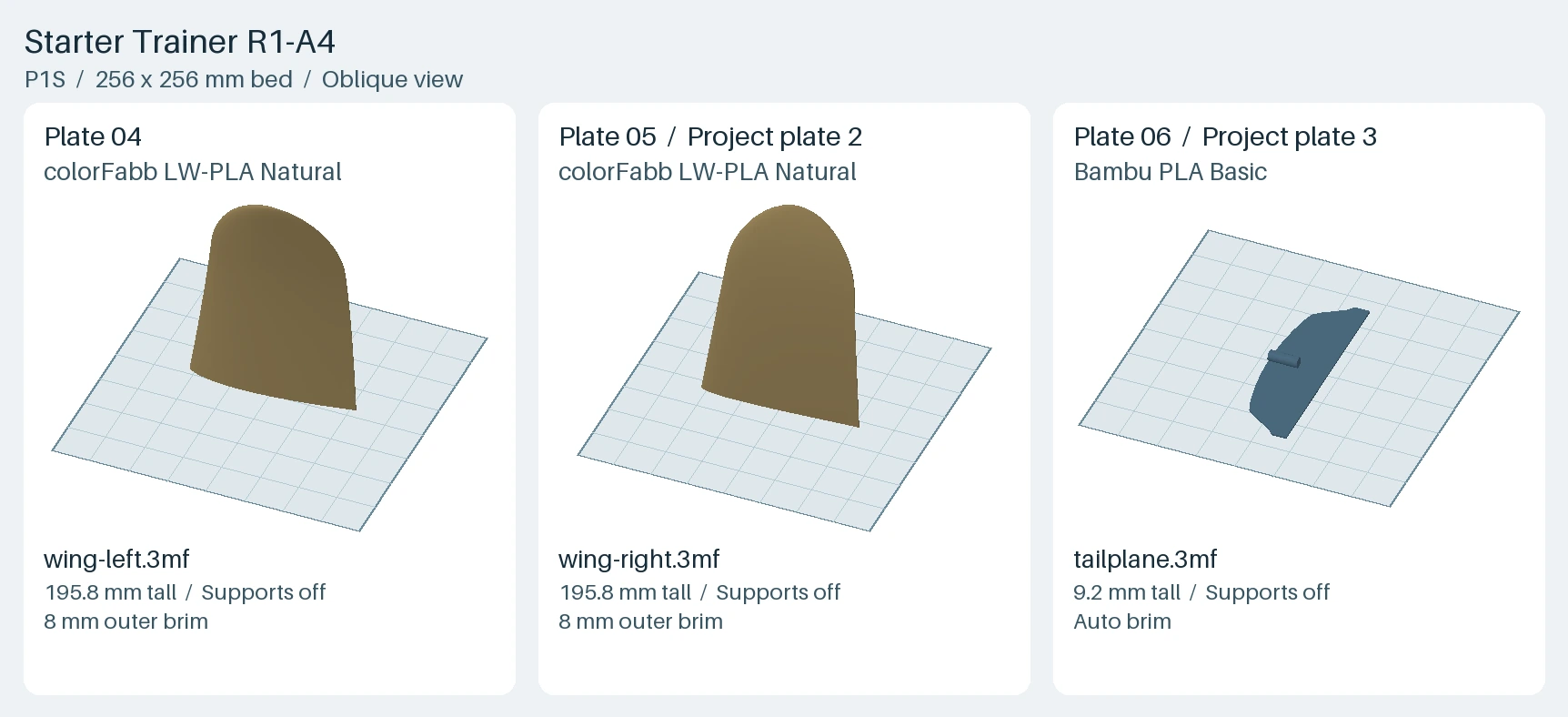
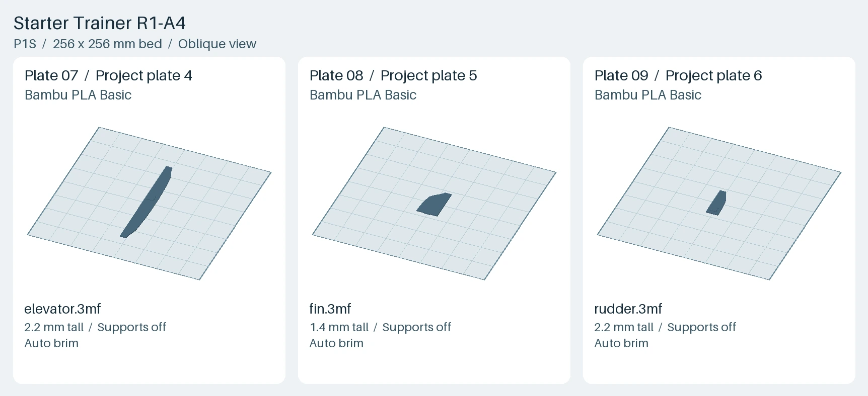
- Use the Wing and Tail project from the kit. Both wing panels use the colorFabb LW-PLA Natural profile. The wing and tail plates print without supports.
View the 9 printed parts
Images show the exported meshes for this revision. Each part is shown at its own scale.
| Part and STL filename | Image | Quantity | Material |
|---|---|---|---|
Pod bodybody.stl | 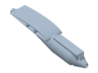 | 1 | Bambu PLA Basic |
Hatchhatch.stl | 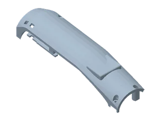 | 1 | Bambu PLA Basic |
Servo trayservo-tray.stl | 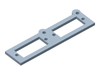 | 1 | Bambu PLA Basic |
Left wingwing-left.stl | 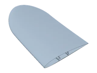 | 1 | colorFabb LW-PLA Natural |
Right wingwing-right.stl | 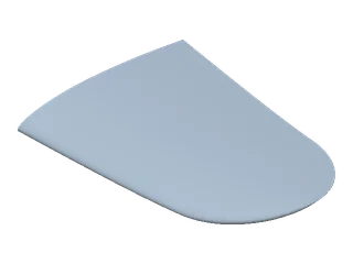 | 1 | colorFabb LW-PLA Natural |
Tailplanetailplane.stl | 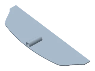 | 1 | Bambu PLA Basic |
Elevatorelevator.stl | 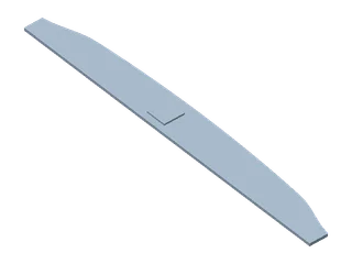 | 1 | Bambu PLA Basic |
Vertical finfin.stl | 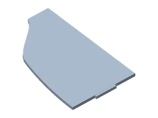 | 1 | Bambu PLA Basic |
Rudderrudder.stl | 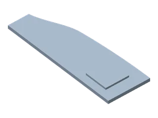 | 1 | Bambu PLA Basic |
Workshop tools
Use your existing workshop equipment where suitable. The reference printer and these tools are budgeted separately.
- A3 setup equipment: Compatible HobbyEagle USB adapter and data cable with the A3 Configurator, or Program Card X. Include the receiver binding accessory if supplied. Use the USB adapter and data cable supplied with the A3 Mini Standard Edition. Program Card X is optional. Reference for A3 setup equipment
- Assembly tools: Use calipers, a straightedge, tools for safe carbon cutting and deburring, support-removal tools, small drivers, and a suitable insert tool.
- Electrical tools and failsafe test lead: Multimeter, soldering and heat-shrink tools, and a signal-only iBUS break that preserves the supply and return. A wattmeter and restrained fixture are needed for later propulsion review. Use existing bench tools if available. Select or assemble the break lead only after confirming the actual signal pin and connector keying.
- Balance and control measurement tools: Scale, padded CG stand, straightedge, incidence gauge and throw gauge or ruler. Set the paired CG supports 60 mm from the centerline. Standard workshop tools are suitable if the stand supports can be spaced as specified.
Bill of materials
Aircraft parts, assembly supplies, and radio and charging gear for revision R1-A4.
Printed-part images show the exported meshes. Hardware and supply drawings help identify items. Images are not to scale.
Download BOM (CSV)Scroll each table sideways to see specifications and supplier links.
Printed parts and filament3 items
| Item | Image | Qty | Price (USD) and stock | Specification & sourcing |
|---|---|---|---|---|
| Pod body, hatch and servo tray | Pod body shown | 1 each | $2.97 165.09 g at $0.018/g $17.99 / 1000 g spool In stock Recheck stock · In stock at last check | Bambu PLA Basic, 1.75 mm. Use the R1-A4 body, hatch and tray STLs or the editable three-plate project. Print the body first. Body and hatch have build-plate-only supports. The servo tray prints without supports. The order link is for the PLA Basic filament. Print the three parts from the revision files. Gray PLA Basic 1.75 mm, 1 kg with spool. The same spool supplies the tail. |
| Left and right wing panels | Left wing shown | 1 each | $1.80 51.4 g at $0.035/g $26.25 / 750 g spool In stock Recheck stock · In stock at last check | colorFabb LW-PLA Natural, 1.75 mm. Use the separate foaming profiles in the kit’s wing and tail project. The 440 mm assembled wing uses the original panel geometry. Measure actual mass, shell quality and bond strength. The order link is for the 750 g LW-PLA Natural spool. Print both panels from the revision files. Natural 1.75 mm, 750 g, SKU 8719033556799. The listing showed a sale price and 275 in stock. |
| Tailplane, elevator, fin and rudder | Tailplane shown | 1 each | $0.38 20.86 g at $0.018/g $17.99 / 1000 g spool In stock Recheck stock · In stock at last check | Bambu PLA Basic, 1.75 mm. Use the retained wing and tail project. Each retained tail plate prints without supports. Use the same PLA Basic spool as the pod. Print the four parts from the revision files. Material use from the same gray PLA Basic spool as the pod. |
Propulsion and onboard electronics9 items
| Item | Image | Qty | Price (USD) and stock | Specification & sourcing |
|---|---|---|---|---|
| HobbyEagle A3 Mini | 1 | $37.12 / stabilizer In stock Recheck stock · In stock at last check | Six-axis airplane stabilizer, 30 × 19.5 × 7.5 mm nominal case, with the supplied thin mounting pad. In-stock Standard Edition, seller SKU 76245. | |
| FlySky FS-X6B | 1 | $11.98 / receiver In stock Recheck stock · In stock at last check | AFHDS 2A receiver with iBUS and both factory antennas. CAD envelope is 36 × 22 × 7.5 mm. Check the delivered board, iBUS plug orientation, antenna exits and retention. The in-stock FS-X6B is the AFHDS 2A receiver with iBUS, seller SKU SS-202607SID672. | |
| Receiver-to-stabilizer lead | 1 | Source to choose | Three-wire iBUS harness from FS-X6B iBUS to A3 Mini Serial RX. Match signal, supply and return on the delivered hardware. Plug keying, pin order, lead length and minimum bend radius require a fit check. Compare the supplied leads on both units. Choose or make a harness that matches the marked pin order, connector keying and installed length. Check the supplied leads and select the length and keying after fitting the receiver and stabilizer. | |
| Hitec HS-40 micro servos | 2 | $15.99 / servo 2 × $15.99 = $31.98 In stock Recheck stock · In stock at last check | Analog 4.8–6.0 V servos. Use two supplied one-sided arms and their center screws. Forward servo drives the elevator, aft servo drives the rudder. The exact HRC31040S listing showed four units in stock. Budget two servos. | |
| E-flite EFLA1010 speed controller | 1 | $24.99 / ESC In stock Recheck stock · In stock at last check | 10 A Pro BEC brushless ESC with factory JST battery lead, 2 mm phase bullets and regulated receiver/BEC lead. Fit the mating XT30 pigtail to the ESC input and check clearance under the hatch. Verify BEC voltage under servo load and the 2S cutoff. Order SKU EFLA1010 with the factory JST battery input. The XT30 conversion parts are listed separately. The retailer showed EFLA1010 in stock for shipping. Horizon Hobby lists this model as discontinued. | |
| E-flite Park 250 outrunner | 1 | $44.99 / motor In stock Recheck stock · In stock at last check | EFLM1130, 2200 Kv with 2 mm phase bullets and a 2 mm shaft. Use the fixed-housing tube mount. The manual specifies 7 A continuous, 8 A for up to 15 seconds and 55 W input. Exact EFLM1130 with 2 mm bullets, listed in stock. | |
| Propeller, adapter and keeper | 1 set | $3.80 / 2-pack In stock · Required quantity unconfirmed Recheck stock · In stock at last check | GWS 6 × 5 slow-fly (GW/EP6050, retailer code 55366050) is the fit reference. Match its hub to the Park 250 adapter and keeper. Check adapter and keeper fit, retention and the full propeller sweep with the pack unplugged. Remove the propeller for powered radio checks. Measure loaded current in a restrained test. The order link covers the GWS propeller. Select the adapter and keeper after measuring the prop hub and shaft. In-stock GWS 6 × 5 slow-fly propeller 2-pack, item 55366050. Select the adapter and keeper after checking the fit. | |
| Lumenier 10188 flight battery | 1 | $13.49 / battery In stock Recheck stock · In stock at last check | 2S 300 mAh LiPo, 48 × 17 × 12 mm nominal, 18 g published, with XT30 main and separate balance lead. Use the delivered contacts and marked polarity to select the mating parts. Order SKU 10188 with XT30. The Lumenier pack with a JST main plug is a different variant. Exact SKU 10188, 2S 300 mAh with XT30, listed in stock. | |
| Mating XT30 pigtail and wire insulation | 1 pigtail plus insulation | $1.79 / pigtail In stock · Required quantity unconfirmed Recheck stock · In stock at last check | Match the delivered battery XT30 contacts and polarity. Use heat-shrink on each ESC-side joint and fit protection at the motor lead exit. Verify withdrawal, polarity, bend radius and strain relief in the actual hatch. The order link covers an XT30 male lead with exposed pins for the ESC side. Confirm the battery's delivered contacts and polarity, then size the heat-shrink to the actual joints. The 10 cm 18 AWG XT30 male lead showed 91 in stock. Select insulation to fit the joints. |
Airframe stock and linkages8 items
| Item | Image | Qty | Price (USD) and stock | Specification & sourcing |
|---|---|---|---|---|
| Wing spar | 1 | $4.64 / 1 m tube In stock Recheck stock · In stock at last check | 5 mm OD × 3 mm ID carbon tube. CAD cut is 190 mm. Order 5 mm OD × 3 mm ID stock and cut it to length. The in-stock 5 × 3 × 1,000 mm tube supplies the 190 mm cut. | |
| Wing locator | 1 | $1.35 / 500 mm rod In stock Recheck stock · In stock at last check | 2 mm solid carbon rod. CAD cut is 70 mm. Order solid 2 mm stock and cut it to length. The in-stock 2 × 500 mm solid rod supplies the 70 mm cut. | |
| Tail boom | 1 | $1.25 / 250 mm tube In stock Recheck stock · In stock at last check | 6 mm OD × 4 mm ID carbon tube. The modeled cut length is 222 mm. Measure both socket engagements before cutting. Order 6 mm OD × 4 mm ID stock and cut it after the socket fit check. The selected 6 × 4 × 250 mm variant showed 96 in stock. It supplies the 222 mm cut. | |
| Motor mount tube | 1 | $6.34 / 1 m tube In stock Recheck stock · In stock at last check | 8 mm OD × 6 mm ID carbon tube. The modeled cut length is 30 mm. Verify engagement on the fixed Park 250 housing, anti-rotation and rotor clearance. Order 8 mm OD × 6 mm ID stock and cut it after measuring the fixed motor housing. The in-stock 8 × 6 × 1,000 mm tube supplies the 30 mm cut. | |
| Micro pushrod system | 1 kit | $8.55 / kit In stock Recheck stock · In stock at last check | DU-BRO #847. Two 20 in × 0.032 in wires, guides, horn-end links and servo-arm connectors. Measure actual sleeves. The modeled fit allows a sleeve up to 2.8 mm OD. Trim both continuous runs to the installed horns. The exact DUB847 kit contains two 20-inch, 0.032-inch pushrods and guides. | |
| Control horns | 2 | $1.49 / 2-pack In stock Recheck stock · In stock at last check | DU-BRO #848 glue-in horns, one on the elevator and one on the rudder. Exact DUB848. One 2-pack covers both controls. | |
| Hinge tape | 1 roll | $5.95 / 15 ft roll In stock Recheck stock · In stock at last check | DU-BRO #916 electric flyer hinge tape for the elevator and rudder. Check adhesion and both surfaces’ free travel on the actual prints. The in-stock DUB916 listing is one 15-foot roll. | |
| Sleeve ties | As needed | $1.79 / 100-pack In stock Recheck stock · In stock at last check | Thin no-crush ties for both forward sleeve anchors and the two exposed-boom stations. Use ties up to 2.5 mm wide and 1 mm thick. Verify sleeve retention and free movement with the ties fitted. HellermannTyton T18R0C2 is one option. Keep the loop loose enough to avoid pinching either pushrod sleeve. T18R0C2 100-pack was listed in stock and ready to ship. |
Fasteners and assembly supplies7 items
| Item | Image | Qty | Price (USD) and stock | Specification & sourcing |
|---|---|---|---|---|
| Body heat-set inserts | 5 installed plus test spares | $11.50 / 100-pack In stock Recheck stock · In stock at last check | CNC Kitchen M2 × 3 mm brass. Three for the hatch and two for the independent tray. Test insert fit in a printed 3.2 mm pilot with 4.5 mm depth before installing inserts in the pod. Order the M2 × 3 mm variant. One pack covers the five installed locations and fit tests. Exact TC-M2x3.0 brass inserts. One in-stock 100-pack covers installed parts and fit samples. | |
| Hatch and servo-tray screws | 5 | $3.40 / three 10-packs In stock Recheck stock · In stock at last check | M2 socket-head screws. Hatch takes one 6 mm, one 8 mm and one 12 mm screw. Tray takes two 6 mm screws. Confirm head seating, driver access, thread engagement and no bottoming. The assortment contains the three specified lengths. Select only 6, 8 and 12 mm screws for this assembly. Choose the 10-pack at each length. DIN 912 A2 M2 × 6, 8 and 12 mm variants were available at $0.96, $1.10 and $1.34. | |
| Servo-ear fasteners | 4 positions | Source to choose | Fit M2 fasteners in the 2.2 mm tray holes, two per servo. Select matching washers or nuts if required. Final head and grip length depend on the actual servo ears and clearance. Measure the case ears and available grip before choosing a screw length and washer or nut combination. Measure grip and clearance before selecting the M2 length and matching washers or nuts. | |
| Battery cinch strap, roof pad and end shims | 1 strap, 1 pad, 2 shims | $7.39 / 12 ft roll In stock · Required quantity unconfirmed Recheck stock · In stock at last check | Soft hook-and-loop strap up to 8 mm wide at X65, a nonabrasive roof pad and trapped fore/aft foam shims. Secure the pack independently of the hatch and verify that the wrapper and connectors cannot chafe. The order link covers reusable hook-and-loop stock for the strap. Trim a strip to at most 8 mm wide and select the pad and shims after dry fit. The black 12-foot One-Wrap stock was listed in stock. Select the roof pad and shims after fitting the pack. | |
| Receiver and ESC retention and wire protection | As needed | Source to choose | Mounting pads or restraints, service slack, chafe protection and harness strain relief. Select exact materials and thickness after checking board clearance, ESC cooling and hatch access. Choose the restraint thickness and wire protection after checking the actual bay fit. Select mounting pads, restraints and wire protection after checking the installed clearances. | |
| Bonding epoxy | As needed | $11.99 / 8 oz set In stock Recheck stock · In stock at last check | Z-Poxy 30 Minute is an option for bonding carbon to printed parts. Test adhesion on the actual carbon and printed material. Follow the epoxy maker’s preparation and cure instructions. In-stock Z-Poxy PT-39 30-minute epoxy. Estimate uses one 8 oz set of this option. | |
| Motor-mount RTV | As needed | $9.65 / 90 mL tube In stock Recheck stock · In stock at last check | DOWSIL 737 is a neutral-cure sealant option for the fixed motor housing mount. Verify retention and anti-rotation with the installed tube and housing. The order link selects the clear 90 mL DOWSIL 737 tube. The selected RTV737-30ZCLR, clear 90 mL tube, was available. Estimate uses one tube of this option. |
Radio and charging gear3 items
| Item | Image | Qty | Price (USD) and stock | Specification & sourcing |
|---|---|---|---|---|
| FlySky FS-i6X transmitter and AA cells | 1 transmitter, 4 AA | $59.90 / transmitter $1.50 / 4 AA alkaline batteries In stock Recheck stock · In stock at last check | Mode 2, AFHDS 2A. Confirm binding to the exact FS-X6B and set CH3 failsafe to motor stop. The link selects Mode 2 Only i6X. Source the X6B receiver and four AA cells separately. The Mode 2 Only i6X variant and the separate Energizer E91 four-pack were both available. | |
| 2S LiPo balance charger | 1 | $59.99 / charger In stock Recheck stock · In stock at last check | Hitec RDX1 Mini #44295 supports 2S LiPo balance charging and low charge-current settings. Verify the delivered balance connector and the pack maker’s permitted charge rate. Use a fire-resistant charging setup. Exact Hitec 44295 RDX1 Mini, listed in stock. | |
| Charger lead | 1 | $10.99 / adapter In stock Recheck stock · In stock at last check | Hitec #44185 XT60-to-XT30 charge adapter. Match the pack’s separate balance connector to the charger and use a matching balance adapter if needed. Check mating contacts and polarity against both the charger and delivered pack. The order link covers Hitec #44185. Verify the pack's separate balance connector before ordering an additional adapter. Exact Hitec 44185 XT60-to-XT30 adapter listed in stock. Check whether the pack needs a separate balance adapter. |
Build guide
Start with the pod of the 440 mm Raven Trainer. Check the fit and clear the passages before printing the wings and tail. Keep the battery unplugged and propeller off during assembly.
Bambu Lab P1S with a 0.4 mm nozzle and textured PEI. Print the pod parts in Bambu PLA Basic at 0.20 mm. Use the saved profiles for the colorFabb LW-PLA Natural wings and PLA Basic tail. Review the print inventory and bill of materials before starting. Use the 3D assembly reference to find parts on the aircraft. The plate images show how parts sit on the printer bed.
Explore the assembly, exploded view and components in 3D
Open full-window 3D referencePrint and clear the pod
- Why this matters
- The first pod print lets you check access and hatch fit before spending time on the wings and tail.
- Where to look
- Use the first plate drawing for the body, hatch and servo tray. On the printed body, start at the open belly and follow the motor lead passage toward the nose and the pushrod passages toward the boom.
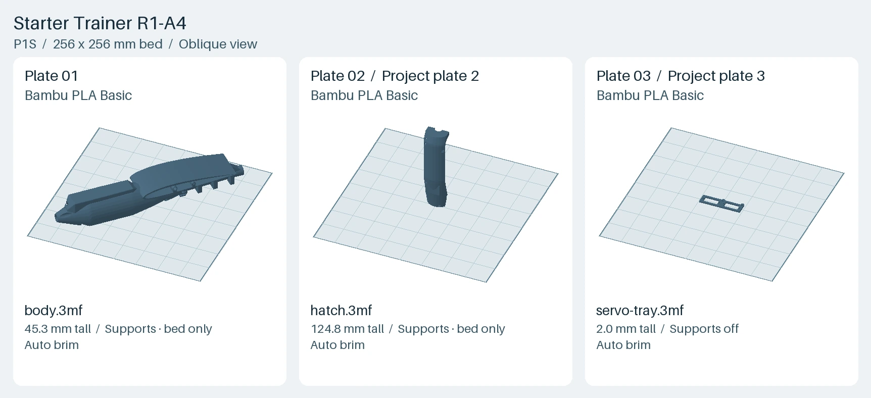
- Open the three-plate Pod Fit project and preview supports on the body and hatch. The body sits diagonally on its belly.
- Remove support through the open belly, especially around the battery pocket and motor lead passage. Clear the antenna exits, pushrod passages, strap slots and insert pilots. Dry-fit the empty hatch. The narrow seam is intentional.
- Print the six wing and tail parts from the R1-A1 Wing and Tail project supplied in the kit. Inspect the wing walls, match the roots and weigh the cleaned parts.
Before you continue
Dry-fit the empty hatch and record its seam at the front, sides and rear. It should seat and lift out by hand before the screws are fitted. Check the strap slots, wire routes and all five insert pilots for remaining support or damage. Test an insert on a coupon of the actual printed material before installing the pod inserts.
Dry-fit the wing and tail
- Why this matters
- Dry-fitting means assembling without glue. It lets you compare the wing angles and align the tail while you can still separate the joints.
- Where to look
- In the wing-root drawing, the large spar and smaller locator pass through separate holes across the pod. The tail boom runs front to back. Use the Fit the boom and moving tail view to see the tail parts and their hinge lines.
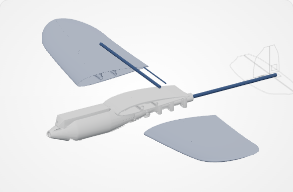
- Square and deburr the carbon stock. Pass the 190 mm spar (5 mm outside, 3 mm inside) and 70 mm solid locator (2 mm) through separate bores. Seat both roots by hand and check even seams and matching incidence.
- Dry-fit the one-piece 6 × 4 mm carbon boom through the rear bridge and into the tail socket. Check engagement at both ends before cutting the modeled 222 mm length. Align the tailplane and fin and measure wing-to-tail incidence.
- Fit the tape hinges and mark the pads from the supplied DU-BRO #848 horns. Check free movement through the nominal 1 mm hinge gaps. Hold each surface flush while fitting its linkage. Check the printed-to-carbon joints and horn bonds before loading them.
Before you continue
Seat both roots on the 190 mm spar and 70 mm locator without forcing them. Record root seams, spar engagement and matching incidence. Measure both boom socket engagements before cutting the 222 mm trial length, then check tailplane and fin alignment. Record the material, adhesive, cure and retention checks for the wing, boom and tail joints before permanent assembly. Check that the surfaces move freely after those joints are secured.
Mount the servos and fit the pushrods
- Why this matters
- The servo tray holds the arms in position and the sleeves guide the moving rods. If the sleeves shift, some of the servo motion can be lost before it reaches the tail.
- Where to look
- Start with the tray and lower hatch in the separated pod drawing. Follow the forward servo to the elevator and the aft servo to the rudder. The Fit the pushrods and guide anchors view shows the sleeves continuing through the rear bridge to the boom.
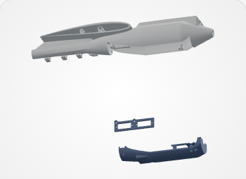
- Test an M2 × 3 mm heat-set insert in printed material before fitting the five pod inserts. Use three hatch screws and two tray screws. Check seating, thread engagement and driver access.
- Secure both HS-40s at their four mounting ears. Install the single arms with their center screws. Point the forward elevator arm toward the belly and the aft rudder arm toward the top of the pod.
- Route the two #847 sleeves through the forward anchors and three pairs of 3.5 mm bridge pilots. Secure them at both marked boom stations without crushing them. Connect the rods at neutral. With the hatch on, check free travel, play and sleeve movement.
Before you continue
Verify the two tray screws secure the tray to the body and all four servo-ear screws and both arm screws remain accessible. Check the sleeves at the forward anchors, all three pairs of bridge guides and both marked boom stations. With the hatch fitted, move each control and both together through the measured travel. Record sleeve movement, play and neutral return. Stop if an arm rubs, a guide slips or a surface binds.
Fit the stabilizer, receiver and antennas
- Why this matters
- The stabilizer needs to face the correct way to sense pitch and yaw. Checking the antenna route with the hatch fitted also catches bends and pinches before the installed radio range check.
- Where to look
- In the cutaway, the A3 Mini sits flat on the lower mount with its arrow toward the printed nose. The receiver sits above and farther forward. Use the two antenna exits view to trace the leads out past the hatch.
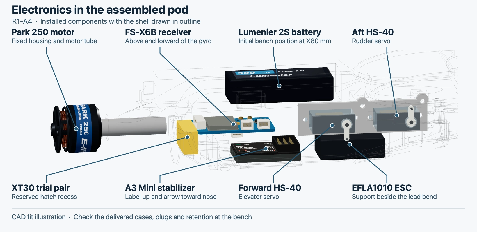
- Fit the A3 Mini flat on its lower mount with the supplied thin pad, label up and arrow forward. Keep its plugs, LED and button accessible.
- Fit the FS-X6B above and forward with iBUS opposite the antenna exits. Leave a service loop for the hatch and keep both leads clear of the seam.
- Set the active antenna ends 90° apart and at least 10 mm from carbon or metal. Check plug and lead bends before securing them. Use this placement for the range test.
Before you continue
Check the arrow, plug access and the position of both active antenna ends before securing the units. Confirm the hatch can open without tugging the antenna leads.
Fit the motor, ESC and battery
- Why this matters
- Check that the motor mount holds, the battery has its own restraint and the main plug can be disconnected with the electronics installed.
- Where to look
- Start at the printed nose in Fit the motor tube and phase leads. Follow the leads back to the speed controller, then use Fit and secure the battery to locate the pack and its strap under the belly hatch.
- Dry-fit the 8 × 6 mm carbon tube in the fixed Park 250 housing. Check engagement before cutting the modeled 30 mm length. Feed each insulated 2 mm phase connector through the 6 mm nose passage separately. Check chafe protection, rotor clearance and retention against pullout and rotation.
- Seat the EFLA1010 on its support without forcing the leads. Dry-fit an unplugged XT30 pair to check the hatch recess, finger access and plug withdrawal. Keep the gyro plugs accessible and leave room for ESC cooling.
- With the hatch off, insert the unplugged battery centered at X63 mm aft of the printed nose. Slide it to X80 mm for the first fit. Use the X65 strap, roof pad and trapped foam end shims to retain it independently of the hatch. Check hatch closure, connector access and lead slack.
Before you continue
With the pack unplugged and propeller removed, measure the motor tube engagement and check its joint for pullout or rotation. Check the actual pack restraint at both usable travel limits with the hatch open, including the strap, pad and trapped end shims. Close and reopen the three-screw hatch to verify plug access, lead slack and insert seating. Record the screw lengths and engagement and stop if a boss cracks or an insert turns.
Connect the radio and power wiring
- Why this matters
- The drawings identify the destinations for power and signal leads. Follow the actual pin markings so that a plug that physically fits also makes the intended connection.
- Where to look
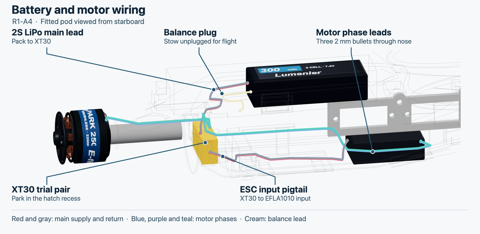
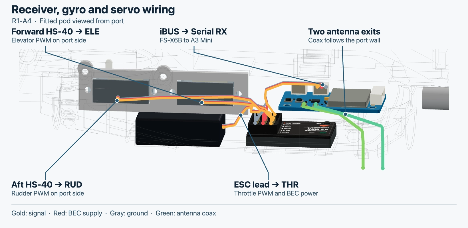
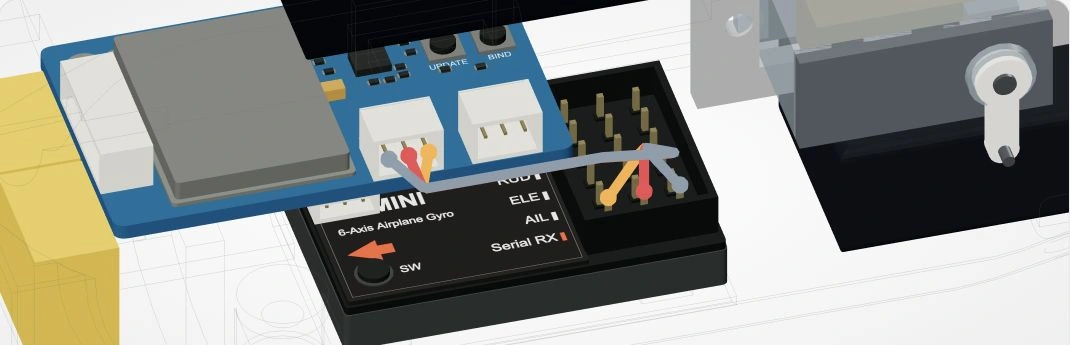
- Start with the full-airframe drawing to locate the pod. The right-side view shows battery and motor power, the left-side view shows the radio and servo leads, and the iBUS close-up identifies the receiver-to-stabilizer pins.
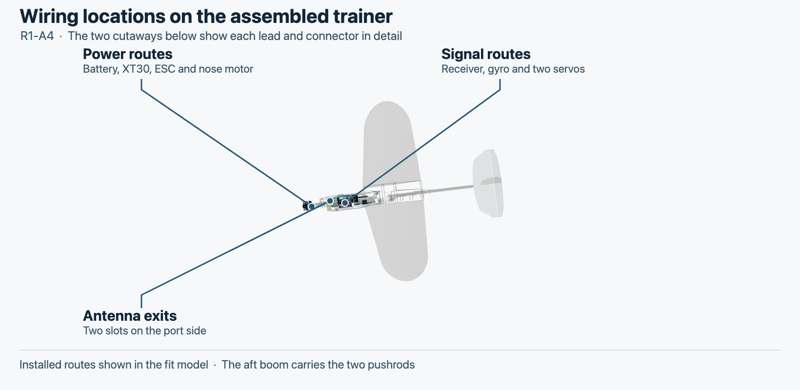
- With the battery disconnected, match the replacement ESC-side XT30 to the pack contacts and verify polarity with a meter. Insulate each joint separately. Keep the balance plug accessible.
- Match the radio leads to the hardware markings for signal, supply and return. Keep the harness clear of the servo arms and pushrods. Check slack with the hatch on.
- Check rotation with the propeller off. To reverse the motor, disconnect power and swap any two phase leads.
Before you continue
Verify XT30 polarity with a meter before connecting the pack. With the hatch closed, make sure plugs stay seated and the harness leaves both servo arms and pushrods free.
Connection map
- FS-X6B iBUS → A3 Mini Serial RX
- Forward HS-40 → A3 Mini ELE
- Aft HS-40 → A3 Mini RUD
- EFLA1010 receiver/BEC lead → A3 Mini THR
- 2S battery XT30 → EFLA1010 main input
- Three EFLA1010 phase bullets → Park 250 motor bullets
Check balance and control movement
- Why this matters
- Weighing records the total mass. The balance check shows whether the secured battery can bring the assembled aircraft into the provisional balance range.
- Where to look
- Use the diagram to mark both support points from the printed nose and centerline. The Check the assembled trainer view also shows the tail travel marks. If you use a cradle to weigh the model, zero the scale with the empty cradle on it first.
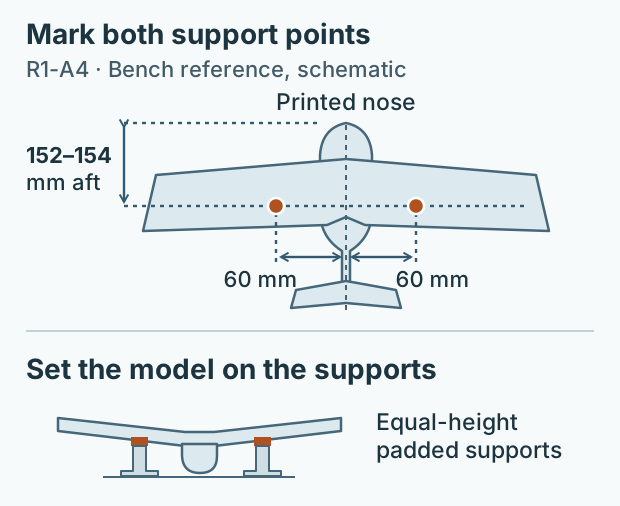
- Weigh with the pack secured and unplugged and the hatch shut. Use X152–154 mm aft of the printed nose as the initial balance reference. Set padded supports 60 mm from centerline and 28.4–30.4 mm behind the local leading edges.
- Move the pack forward for tail drop or aft for nose drop. Secure it, check lead slack and recheck with the hatch shut. Correct the installation if battery travel cannot reach the target.
- Remove the propeller and restrain the aircraft. Start the A3 with the airframe still, throttle at verified idle and both surfaces centered. Check 50 Hz servo output, 2S cutoff and BEC voltage under both servo loads.
- In GYRO OFF, check elevator up on pullback and rudder right from behind on right command. Check opposite directions. For the propeller-off setup, start with ±10° elevator and ±13° rudder. In NORMAL, check that correction opposes pitch and yaw. With the hatch shut, check neutral return and free travel with stick and gyro inputs combined.
Before you continue
Record the exact A4 body and retained wing and tail parts, printed materials and profiles, stock dimensions, joint engagement, adhesive and cure. Add measured mass, balance, secured battery position and control travel. Recheck wing and tail alignment, tube retention and neutral return after opening and refitting the hatch. Stop if a joint moves, a guide slips, a control binds or the battery travel cannot reach the bench balance reference.
Verify failsafe and record your measurements
- Why this matters
- A loss of radio signal and a break between the receiver and stabilizer are separate faults. Check both and record the result for each.
- Where to look
- Use the iBUS close-up to locate the link from the FS-X6B receiver to A3 Mini Serial RX. Keep the propeller off for both checks and disconnect the pack before inserting the signal break.
- Keep the propeller off. Verify throttle cut and set FS-i6X CH3 failsafe to the confirmed motor-stop output. At low motor speed, test transmitter loss and confirm the motor stops.
- With the pack unplugged, fit an iBUS signal-only break between receiver and gyro. Leave supply and return connected. At low motor speed with the radio linked, break iBUS and confirm motor stop. Set idle and engage throttle cut before restoring either link. Check for unexpected restart and verify radio range.
- Record part and aircraft mass, joint fit and retention, balance, usable battery travel, throws and both failsafe results.
- Check propeller, adapter and keeper fit before a restrained propeller-on test. Measure current during the test. Check charging limits, passive stability and trim authority.
Before you continue
The motor must stop for both faults and stay stopped when the link returns with throttle cut engaged. Stop if it restarts. Keep the exact build on the bench until the remaining structural, balance and propulsion checks are reviewed.